
Editors: Tornetta, Paul; Einhorn, Thomas A.; Damron, Timothy A.
Title: Oncology and Basic Science, 7th Edition
Copyright ©2008 Lippincott Williams & Wilkins
> Table of Contents > Section IV – Basic Science > 16 – Biomechanics
16
Biomechanics
Frederick W. Werner
Joseph A. Spadaro
Some Basic Biomechanical Terms
-
Force (load): A force is an action on a body. It has a direction and a magnitude.
-
Oblique forces:
A force being applied at some angle to a coordinate system can be
represented as two perpendicular or orthogonal forces in that
coordinate system.-
Magnitude of the oblique force on the implant is the square root of the sum of the squares of the perpendicular forces (Fig. 16-1).
-
Graphically, the force on the implant is the hypotenuse of the right triangle formed by the perpendicular forces.
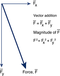 Figure 16-1
Vector addition of two orthogonal forces to obtain the force, F. A
force is represented by drawing either an arrow or line over the letter
corresponding to that force. -
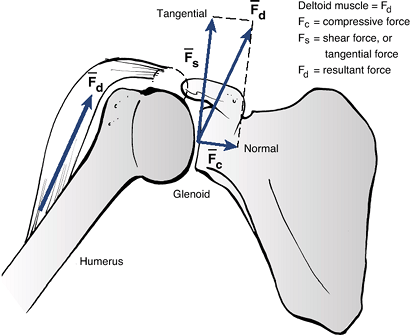
Examples: shoulder joint (Fig. 16-2) and knee joint (Fig. 16-3)
-
-
Dynamic forces: Dynamic forces include the effect of the inertia of the person moving or an impact on an object against another.
![]() Figure 16-2 Example of force decomposition in the shoulder joint. The deltoid force, Fd, is represented (decomposed) as a compressive force, Fc, and a shearing or tangential force, Fs. (Adapted from Buckwalter JA, Einhorn TA, Simon SR, eds. Orthopaedic Basic Sciences, 2nd ed. Chicago: American Academy of Orthopaedic Surgeons, 2000.)P.368
Figure 16-2 Example of force decomposition in the shoulder joint. The deltoid force, Fd, is represented (decomposed) as a compressive force, Fc, and a shearing or tangential force, Fs. (Adapted from Buckwalter JA, Einhorn TA, Simon SR, eds. Orthopaedic Basic Sciences, 2nd ed. Chicago: American Academy of Orthopaedic Surgeons, 2000.)P.368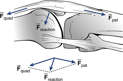 Figure 16-3 Example of calculation of forces in the knee joint. The patellofemoral joint reaction force, Freaction, is the vector parallelogram sum of the quadriceps force, Fquad, and the patellar tendon force, Fpat.
-
Example of normal walking gait:
During gait, the forces on the knee joint are due to the weight of the
person, the muscles causing the knee to move, the ligamentous
structures that provide stability, and the inertia of the person as the
heel strikes the floor and as he or she pushes off before toe off.
-
-
Moment: A
moment is defined as a force being applied at some distance away from
some pivot point. Its magnitude is the force times the moment arm. -
Moment calculation:
If several moments are being applied to a bone or some object in
equilibrium, then the sum of those moments about a given point is equal
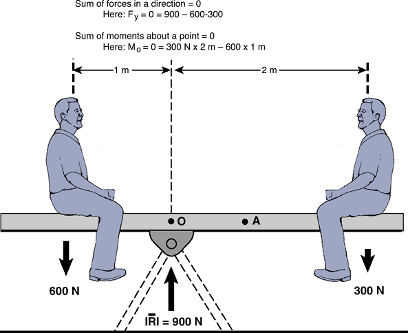
to zero.![]() Figure 16-4
Figure 16-4
Calculation of moments about a pivot point, 0. In a static, nonmoving
situation, the sum of the vertical forces equal 0, and the sum of the
moments about a pivot point equal 0. (Adapted from Buckwalter JA,
Einhorn TA, Simon SR, eds. Orthopaedic Basic Sciences, 2nd ed. Chicago: American Academy of Orthopaedic Surgeons, 2000.)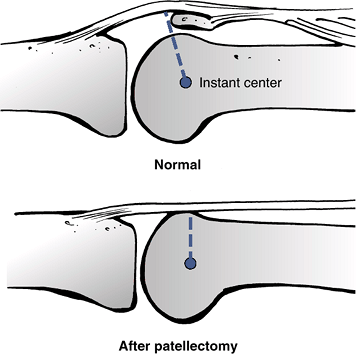 Figure 16-5
After a knee patellectomy, the moment arm for the knee extension moment
is decreased. Therefore, the quadriceps force required to extend the
knee has to be larger than before patellectomy. (Adapted from Nordin M,
Frankel VH, eds. Basic Biomechanics of the Musculoskeletal System, 2nd ed. Philadelphia, Lea & Febiger, 1989.)-
Examples: using a see-saw (Fig. 16-4), the knee joint (Fig. 16-5)
-
-
Torques: A
torque is typically caused by a twisting motion such as opening ajar.
There is an equal but opposite torque required to resist the torque
being applied to open the jar.-
Torque = applied force × the moment arm
-
-
Units: Forces
are typically measured in Newtons (N). Moments and torques are measured
in Newton-meters (N-m) or Newton-millimeters (N-mm).
P.369
Kinematics
Kinematics is the study of how things move. Motions can
be viewed as displacements (translations), as rotations, or as a
combination of them. A person or object might be moving at a constant
velocity or with a changing velocity, in which case it is accelerating
or decelerating.
be viewed as displacements (translations), as rotations, or as a
combination of them. A person or object might be moving at a constant
velocity or with a changing velocity, in which case it is accelerating
or decelerating.
-
Velocity: The
rate (speed) and direction of movement of an object, such as a car
moving down the road. The magnitude of the velocity is the distance or
displacement of the object per unit time. -
Acceleration and deceleration: If the speed of that object, or its direction, is changing, then the object is either accelerating or decelerating.
-
Center of rotation:
For most joints in the body, one can find a center of rotation about
which the bone is rotating. For example, door hinges are the fixed
center of rotation for a rotating door. In the knee joint and many
others, the center of rotation is not fixed but changes through the
range of knee flexion. -
3D center of rotation:
In the knee joint as well as in other joints in the body, the motion is
not necessarily planar. As the knee flexes and extends, tibial rotation
and ab/adduction cause the center of rotation to move in three
dimensions.
Mechanical Properties of Materials
-
Stress: A force applied to an implant or bone will cause a stress in the material.
-
Stress = applied force divided by the area over which the force is being applied (typical units are N/mm2)
-
-
Strain: When
a force or stress is applied to some implant or bone, there will be a
small deformation. To normalize that deformation, a strain is computed.-
Strain = change in length (AL) divided by the original length (Lo); typical units are mm/mm
-
-
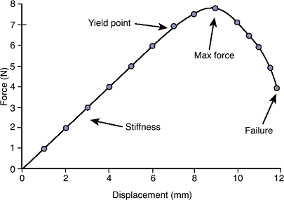
Force-displacement (loading) curve (Fig. 16-6):
Plot of the resultant forces due to an applied displacement to a
structure such as a bone or ligament. It can also be a plot of the
force applied to a structure to produce a displacement.-
Structural properties
![]() Figure 16-6 Example of a force—displacement loading curve for a linear, elastic structure.
Figure 16-6 Example of a force—displacement loading curve for a linear, elastic structure.-
Stiffness: slope of the linear portion of the force—displacement curve
-
Yield point: force at which the structure starts to plastically (permanently) deform
-
Maximum force: maximum force the structure can support
-
Energy: area under the force—displacement curve
-
-
-
Stress—strain curve (Fig. 16-7): A stress—strain curve is computed from a force-displacement curve.
-
Material properties
-
Elastic modulus: slope of the linear portion of the curve
-
Proportional limit: force at the end of the linear part of the curve
-
Yield point: force at which the material starts to plastically deform
-
Ultimate strength (tensile strength if in tension, compressive strength if in compression): maximum stress the material can support
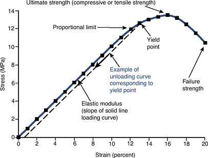 Figure 16-7 Example of a stress-strain loading curve for a linear, elastic material.
 -
-
Toughness: area under the stress—strain curve
-
Ductility:
the ultimate strain (strain at rupture) for a material undergoing
inelastic deformation. Intuitively, how much a deforming material
stretches or deforms before breaking. This is typically described as a
percent elongation or reduction of area.
P.370 -
-
Fatigue properties:
With repetitive loading, materials and structures can fail (fracture)
at forces and moments that are far less than the maximum force due to
the single application of a force. Most implants fail in fatigue.-
Endurance limit: the maximum stress that can be applied an infinite number of times and the material will not fail
-
-
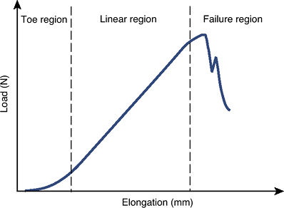
Nonlinear materials (Fig. 16-8):
A material that has an initial nonlinear loading curve (i.e., does not
have a straight-line relationship between force and displacement or
between stress and strain)-
Toe-in region:
Region at the beginning of a typical force—displacement or
stress—strain curve in which the flatness of the curve reflects
considerable displacement or strain with the initial application of
very little force or stress. For example, little force is required to
cause initial displacement in a ligament as the fibers straighten.
-
-
Viscoelastic material properties: Creep and stress relaxation of materials (Fig. 16-9)
-
Viscoelasticity: When material properties and behavior (above) are loading rate-dependent.
True of almost all biological tissues, especially ligaments, cartilage,
and polymeric biomaterials. Their properties change with the speed at
which they are loaded, or with constant loading.![]() Figure 16-8
Figure 16-8
Example of a nonlinear material. Under initial loading, there is some
initial laxity as the material starts to elongate. This region of the
curve is known as the toe-in region, followed by a linear region where
there is a linear elongation response to the applied force. (Adapted
from Buckwalter JA, Einhorn TA, Simon SR, eds. Orthopaedic Basic Sciences, 2nd ed. Chicago: American Academy of Orthopaedic Surgeons, 2000.)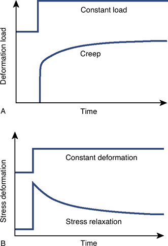 Figure 16-9 Creep and stress relaxation material behavior. (From Mow VC, Hayes WC. Basic Orthopaedic Biomechanics. New York: Raven Press, 1991;203.)
 -
Creep deformation: Under constant load, deformation continues with time until a plateau is reached.
-
Stress relaxation:
After a sudden but then constant deformation, the stress in the
material beneath the deformation will gradually decrease until a
plateau is reached.
-
-
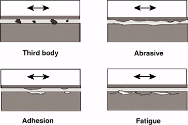
Wear of materials (Fig. 16-10)
-
Three-body wear: Particulate material between adjoining surfaces causes abrasion or accelerated loss of surface integrity.
![]() Figure 16-10 Material wear.
Figure 16-10 Material wear. -
Abrasive wear: One or both of the adjoining surfaces with an uneven texture cause loss of material from the surfaces during movement.
-
Abrasive wear accelerates the destruction
of the natural articular surface when cartilage becomes thin or
subchondral bone is exposed, resulting in “bone on bone.” In artificial
joints, irregularities (asperities) in metal components due to
corrosion or adhesion rapidly abrade an adjacent polyethylene surface.
-
-
Adhesive wear: Portion of one material is in contact with irregularities on opposing material, causing them to adhere to each other.
-
Adhesive wear is an important early wear
mechanism. Ultra-high-molecular-weight polyethylene acetabular cups
have shown such wear leading to formation of a secondary socket and
distortion of mechanical function in total hip joint replacements.
-
-
Fatigue wear:
Material is removed from articulating surfaces after repetitive
excessive stresses cause minute fracturing of the surface layer.-
Fatigue wear generally occurs as a late
failure mechanism. For example, if a polymer component in a joint
prosthesis is too thin, local stresses exerted by a metal component on
the polymer may be greater than with a thicker layer. After many cycles
the fatigue limit of the polymer can be exceeded, leading to cracking
and surface failure of the polymer.
-
-
Hardness: The resistance to surface deformation by indentation or scratching
-
Scratching hardness is commonly quantified using the Mohs original scale:
-
Diamond =10, talc = 1, aluminum = 2 to 3, steels = 5 to 8
-
-
Indentation hardness is quantified by using either a Brinell hardness or Rockwell hardness scale.
-
-
Behavior of Simple Structures
-
Tensile, compressive, bending, and torsional loading
-
Tension: causes material to elongate
-
Compression: causes material to compress (shorten)
-
Bending: causes compression on one side, tension on other side of material
-
Shear: tends to cause distortion of one portion of the material relative to another portion, parallel to the direction of loading
-
Torque: causes material to twist
-
-
Three-point bending (Fig. 16-11): produced by a combination of three parallel forces applied at different points on the structure
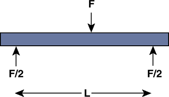 Figure 16-11
Three-point bending. An implant or bone can be exposed to three-point
bending by having an intermediate force centrally located and supported
by two end supports. -
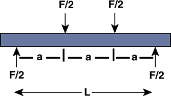
Four-point bending (Fig. 16-12): produced by a combination of four parallel forces applied at different points on the structure
-
Bending stresses:
If a bone is exposed to bending, one side of the bone experiences
tensile stresses, while the other experiences compressive stresses.-
The magnitude of either stress is:Stress magnitude = δ = Mc/I
-
where M is the moment, c is the distance
from the center of the beam or bone where there are no stresses, and I
is the moment of inertia (a descriptor of the beam or bone’s
cross-sectional shape to resist bending; see below).
-
-
Moment of inertia (Fig. 16-13):
The moment of inertia of a bone, structure, or implant is a
characteristic of its cross-sectional geometry and represents the
resistance to bending. For simple cross-sections, this property can be
easily computed. The bending moment of inertia, for example, increases
with the diameter of the bone raised to the fourth power. -
Torsional stresses:
Torques applied to a bone or beam may cause a torsional spiral
fracture. In a beam, the torsional stresses are greatest at the largest
radius from the center of the beam.Stress magnitude = τ = Tc/J![]() Figure 16-12
Figure 16-12
Four-point bending. An implant or bone can be exposed to four-point
bending. Here the distance between the two intermediate forces is the
same as the distance to the end supports.P.372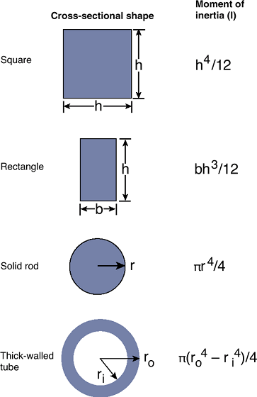 Figure 16-13 Cross-sectional views and the corresponding moments of inertia.
 -
where T is the applied torque, c is the distance from the neutral axis, and J is the polar moment of inertia (see below).
-
Polar moment of inertia (Fig. 16-14):
The polar moment of inertia of a bone, structure, or implant is a
characteristic of its cross-sectional geometry. It represents the
structure’s resistance to twisting under torsional load. For simple
cross-sections, the polar moment property can be easily computed. The
polar moment of inertia of a long bone increases as the diameter raised
to the fourth power. Small changes in the size can have profound
changes in torsional strength.
 |
|
Figure 16-14 Cross-sectional views and the corresponding polar moments of inertia.
|
Suggested Reading
Buckwalter JA, Einhorn TA, Simon SR, eds. Orthopaedic Basic Sciences, 2nd ed. Chicago: American Academy of Orthopaedic Surgeons, 2000.
Mow VC, Huiskes R, eds. Basic Orthopaedic Biomechanics and Mech-ano-Biology, 3rd ed. Philadelphia: Lippincott Williams & Wilkins, 2005.
Nordin M, Frankel VH, eds. Basic Biomechanics of the Musculoskeletal System, 2nd ed. Philadelphia: Lea & Febiger, 1989.