
fixed-angle plate, while used less commonly today, is an excellent
method of treatment for selected subtrochanteric femur fractures (1,2,3,4,5,6,7,8,9,10,11,12,13).
The blade plate has traditionally been used most commonly, but with the
recent development and refinement of locking screw-plate technology,
fixed-angle screw-plate constructs are being used more frequently.
Plate fixation has a long history of successful application for
proximal femur fractures, but instills a certain degree of anxiety
among many surgeons. Outside of trauma centers, fixed angle plates are
infrequently used implants. However, these implants offer several
advantages when compared with other forms of fixation for proximal
femoral fractures (4). They can be used in
severely comminuted fractures, ipsilateral hip and shaft fractures, and
subtrochanteric fractures with extension into the base of the neck or
peritrochanteric region.
qualities found with few other implants. They offer excellent stability
and rotational control in complex fractures, can be used after
corrective osteotomy about the hip, provide immediate fracture
compression through surgeon-controlled application, and can offer
valuable salvage options for failed fixation of other devices used in
the proximal femur. Like any technically demanding procedure, immediate
and long-term outcomes are optimized with experience and mastery of the
surgical technique. Fixed-angle plating is an excellent implant when
using indirect reduction and biological plating of both proximal and
distal femoral fractures (4,14,15).
Indirect reduction and fixation with these devices provide mechanically
sound stabilization, allowing rapid mobilization and early, protected,
weight bearing.
or a fixed-angle locking-screw plate system, is indicated for many of
proximal femoral fractures, including subtrochanteric and
subtrochanteric-intertrochanteric fractures, fractures with extension
into the basilar femoral neck, and some combined femoral-shaft and
femoral-neck fractures. Alternative implants for these fractures
include dynamic condylar screw devices and reconstruction
cephalomedullary nails (5,9,12,16,17).
Relative contraindications to traditional fixed-angle plate
osteosynthesis for subtrochanteric fractures include elderly patients
with osteoporotic
bone
whose poor bone quality may compromise extramedullary fixation
stability; unreliable patients who cannot comply with protected,
postoperative, weight bearing; and surgeons unfamiliar with the
technique.
reduction of the proximal femur with fixed-angle plates: direct or
indirect reduction. Direct reduction is recommended when the injury
involves two main, large fragments (proximal and distal shaft
fragments) and only one or two butterfly fragments with minimal
comminution. Anatomic reduction and individual lag-screw fixation of
the large butterfly fragments can usually be achieved without
difficulty (16). Indirect or biological
reduction is the preferred technique when moderate to severe
comminution is present. In the latter case, anatomic reduction of
individual fragments is technically impossible, and the required
soft-tissue stripping of the fragments leads to devascularization. The
goal of indirect reduction is to restore anatomic length, axis
alignment, and rotation of the extremity, using both the implant and a
femoral distractor in concert (4). The most
appropriate method of fixation is a bridging technique in which a long
plate, with relatively few, well-spaced, possibly locking, screws are
used. Indirect reduction also relies upon the ability of the surgeon to
tension the soft-tissue envelope with distraction of the fracture back
to length with minimal disturbance of the surrounding fracture hematoma
and periosteum.
fixed-angle plate is to be used for proximal femoral fractures. The
surgeon should be familiar with implants and techniques of the AO/ASIF
group before attempting this procedure. To avoid intraoperative
complications, the surgeon must address several key points in
preoperative planning of plate osteosynthesis. If a blade plate is
being planned, the correct insertion site of the blade, the appropriate
length of both the blade and the plate portion of the device, and the
number of lag and plate compression screws are important to consider.
If a locking plate will be used, the surgeon should consider the
proximal or distal position of the plate that is necessary to allow
correct placement of the screws into the femoral neck and understand
that the length of the plate is crucial. The first step in planning
osteosynthesis is to reconstruct the proximal femoral fracture by
drawing all the individual fracture fragments into a reduced position.
Frequently, multiple radiographs of the involved side are required
because of fracture fragment displacement and rotation (Figs. 19.1 and 19.2).
placement of the blade, and thus the next step is to determine the
correct entry site of the seating chisel in the lateral greater
trochanter. Most commonly, this is just proximal and lateral to the
most prominent portion of the greater trochanteric ridge (Fig. 19.3).
Using this landmark will, in the majority of cases, place the blade in
the inferior portion of the femoral head and proximal to the inferior
aspect of the femoral neck.
reduction, AO blade-plate templates can be used to estimate the blade
length and side-plate size. Blade lengths are available in 10-mm
increments, starting at 50 mm, and side plate lengths are determined by
the number of holes, which range from 5 to 26 holes with special order
implants. The blade portion of the plate should reach to within 1.0 to
1.5 cm from the inferior central portion of the femoral-head articular
surface. Estimation of the side plate length and number of screw holes
below the most distal extent of the fracture is possible from the
preoperative plan. At least four screws engaging eight cortices are
necessary distal to a comminuted subtrochanteric fracture.
Alternatively, the plate length may be increased, and screws may be
spaced out along the length of the shaft fragment. This approach
distributes the deforming forces over a greater distance and leads to a
more stable construct. After planning the reduction of the fracture
fragments into an acceptable position and tracing the most appropriate
plate template over the reconstructed femur, the surgeon confirms the
preoperative plan in a step-wise fashion, verifying the implant size,
number of screws above and below the fracture, and the correct
trochanteric entrance site.
 |
|
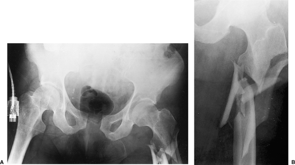
Figure 19.1. A. AP radiograph of the pelvis and (B)
AP radiograph of the proximal left femur, which shows a comminuted, left, subtrochanteric, femur fracture and diastasis of the pubic symphysis in a 79-year-old man. |
device much of the templating is similar to process use for a blade
plate, with several additional issues requiring attention. Once the
fracture is reconstructed on paper the right or left AO template should
be selected, and the appropriate plate length can be determined. Plate
lengths vary from 2 screws to 16 screws along the shaft of the plate.
These newly designed plates have special combination-plate screw holes
that allow either 4.5-mm compression screws or 4.0-mm or 5.0-mm locking
screws to be inserted. Three fixed-angle screws are used for proximal
fixation into the femoral head and neck, at angles of 95 degrees
(7.3-mm screw), 120 degrees (7.3-mm screw), and 135 degrees (5.0-mm
screw). There is little room for adjustment after inserting these
screws once the plate placement is decided, so the correct plate
position on the lateral femoral cortex is necessary. As with a blade
plate, recent improved understanding in biological plating techniques
has indicated that a longer plate with well-spaced screws, leaving
several holes unfilled, is preferable.
lateral decubitus position with cross-table fluoroscopy, or via supine
positioning on a radiolucent fracture table. If lateral positioning is
used, the extremity is prepped and draped free, allowing manipulation
of the fracture fragments and facilitating “frog lateral” views that
provide orthogonal x-ray visualization of the fracture and correct
position of the plate and screws in the proximal femur.
performed, extending from several centimeters proximal to the greater
trochanter to a level distal enough to allow reduction of the side
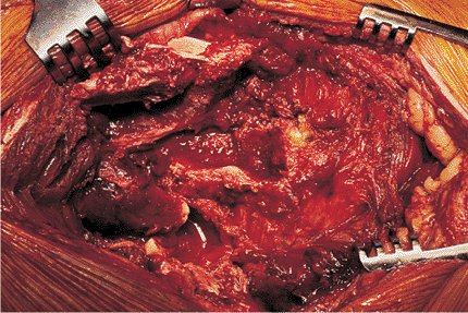
plate to the femoral shaft (Fig. 19.4). After
dissection through skin and subcutaneous tissue, the tensor fascia lata
is incised and the vastus lateralis is released from the
posterior
aspect of the femur and intermuscular septum and reflected anteriorly.
It is important to adequately expose the greater trochanter. During
this dissection, the surgeon should take care to minimize stripping of
individual comminuted bone fragments (Fig. 19.5).
 |
|
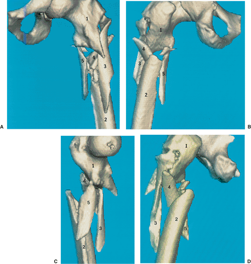
Figure 19.2. Three-dimensional computed axial tomography (CAT) images of the (A) anterior, (B) posterior, (C) medial, and (D) lateral views of the subtrochanteric fracture seen in Figure 19.1.
These views demonstrate comminution of the lateral, proximal, femoral cortex below the lateral trochanteric ridge. Major fragments are numbered 1 to 5 on all views. |
immediately distal to the lateral trochanteric ridge is examined. If
the cortex at this level is compromised, an important anatomic landmark
is lost (see Figs. 19.1 and 19.2). Reconstruction of the proximal, lateral, femoral cortex (see Fig. 19.2, fragment 3, and Fig. 19.3, step 1) to the femoral neck–trochanteric fragment (Fig. 19.2, fragment 1) is crucial if a blade plate is being used
because it recreates the entry point reference for the seating chisel (see Fig. 19.3, step 2 and Fig. 19.6).
When using a locked plate this step is less critical because the
greater trochanter and guide wire position in the neck can be used as a
guide for the correct proximal-distal plate position.
 |
|
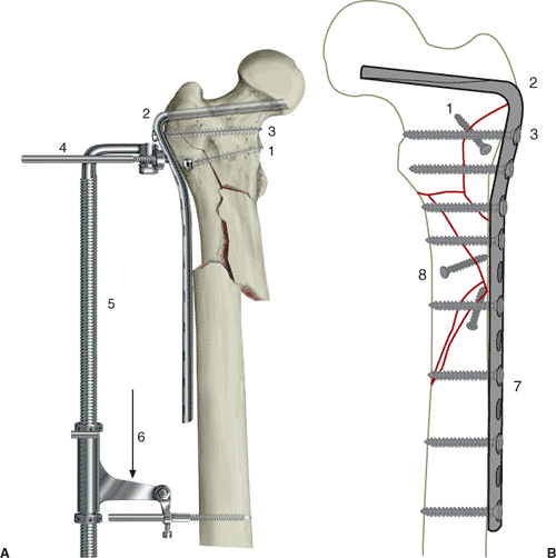
Figure 19.3. A.
Steps used to obtain reduction of the subtrochanteric fracture by using the AO/ASIF fracture distractor. Step 1, reconstruction of the proximal, lateral, femoral cortex with a lag screw. Step 2, cutting and seating of the blade plate into the proximal femur. Step 3, insertion of the first screw of the blade plate to stabilize it in the proximal femur. Step 4, placement of the distractor pin holes, the proximal one in the second hole of the plate and the distal one below the end of the plate. Step 5, application of the AO/ASIF fracture distractor to the pins. Step 6, overdistraction of the fracture. B. Preoperative plan showing the reconstructed, left, subtrochanteric, femur fracture with individual lag screws and blade-plate template traced over the femoral shaft. The size of the blade, number of holes for the side plate, and entrance site slightly proximal to the lateral trochanteric ridge (steps 1 to 3). Stabilizing the plate to the distal shaft and completion of lag-screw and distal-screw fixation (steps 7 to 8). Direct reduction of this fracture is planned with multiple lag-screw fixation of large butterfly fragments and long oblique fracture under the plate. |
implant is to establish fixation into the proximal femoral-head and
femoral-neck fragment; this approach will allow for anatomic fracture
alignment when the distal fragment is reduced to the plate. For blade
plate application, two guide wires are placed initially to direct the
insertion of the chisel. The first wire is placed along the anterior
cortex of the femoral neck to indicate the degree of anteversion and to
dictate the direction of chisel insertion in the anteroposterior (AP)
plane. Alterations to the chisel orientation at this stage will affect
internal or external rotation of the final fracture reduction. The
second wire is placed into the superior portion
of
the greater trochanter at a 95-degree angle to the femoral shaft, and
it is advanced into the femoral neck and head. The second wire controls
the coronal plane alignment of the chisel position and subsequently the
plate position. Miscalculation of this angle will lead to varus or
valgus mal-alignment of the fracture site. An angled guide instrument
(preset to 95 degrees) can aid in the proper insertion angle of this
wire (Fig. 19.7), which should be
placed in neutral or slight valgus alignment to ensure avoidance of
varus coronal alignment. Other anatomic landmarks include the lateral
trochanteric ridge; the lateral, proximal, femoral shaft; and the AP
width of the greater trochanter.
 |
|
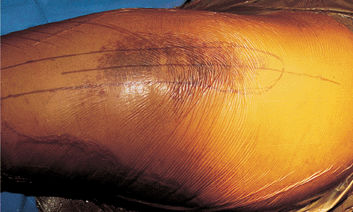
Figure 19.4.
The patient is placed in the lateral decubitus position, and a direct lateral approach is made, extending above the level of the greater trochanter to the proximal third of the femoral shaft. |
 |
|
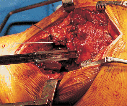
Figure 19.5.
Prereduction exposure of the subtrochanteric fracture. Minimal stripping of individual bone fragments is mandatory to ensure viability of fragments after reduction. |
 |
|
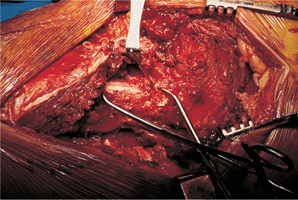
Figure 19.6.
Reduction of the lateral femoral cortex beneath the trochanteric ridge is performed by using large reduction forceps and stabilized with K wires or lag screws. Lag screws are preferable for definitive fixation. Reduction of fragments three and four to the main proximal neck–trochanteric fragment reconstructs the lateral, proximal, femoral cortex. |
 |
|
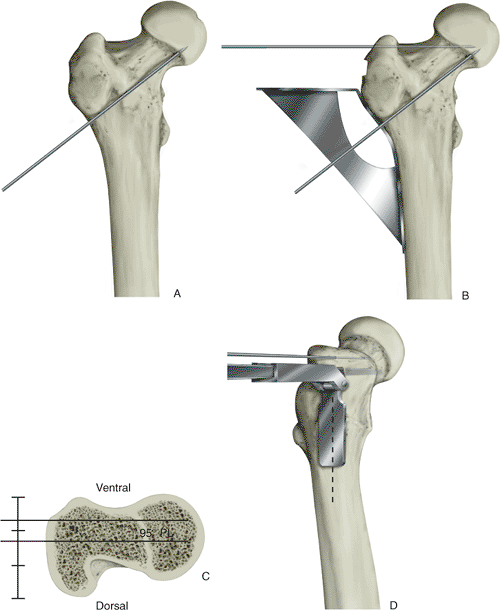
Figure 19.7. Placement of guiding K wires to facilitate cutting of the blade slot into the femoral neck. A. Anterior femoral-neck guide wire indicating femoral-neck anteversion. B. The 95-degree angled guide and placing the corresponding guide wire into the proximal portion of the femoral neck. C.
Relation of the femoral neck to the proximal greater trochanter for insertion of the 95-degree fixed-angle blade plate. Note the central femoral neck corresponds to the anterior half of the greater trochanter at this level. D. Anterior lateral view of the seating chisel placement, cutting the blade slot into the base of the femoral head (note that the flange of the seating guide is in the midportion of the femoral shaft). Reconstruction of the lateral, proximal, femoral cortex enhances the correct position of the seating-chisel guide. |
 |
|
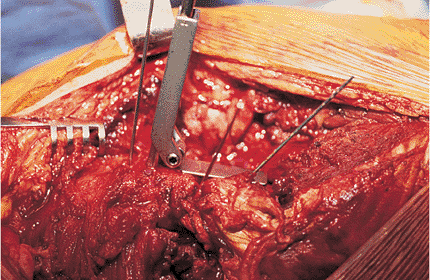
Figure 19.8. Anterior view of the seating chisel and guide parallel to the 95-degree greater trochanteric guide wire.
|
(preset at 95 degrees) under fluoroscopic control. The femoral neck
rises from the anterior half of the greater trochanter; therefore, the
seating chisel should enter the anterior half of the trochanter just
proximal to the lateral trochanteric ridge and not in the anatomic
middle of the trochanter (Fig. 19.7). One of
the more common errors with the use of a blade plate is penetration of
the anterior femoral cortex with the seating chisel, which will result
in plate malposition and an external rotation deformity of the distal
fragment and extremity when the plate is reduced to the shaft. The
weight of the insertion handle has a tendency to fall posteriorly and
direct the chisel anteriorly. This chisel movement can be avoided by
using frequent AP and lateral fluoroscopic imaging as the chisel is
progressively seated into its final position in the femoral neck and
head (Figs. 19.8 and 19.9).
Constant attention to the angle of insertion, rotation of the chisel,
and internal or external torsion of the femur will reduced the risk of
technical errors. The seating chisel has an adjustable flange that is
placed against the lateral femoral cortex inferior to the trochanteric
ridge. This serves as an alignment guide for detection of any internal
or external rotation and any flexion or extension of the chisel as it
is
seated.
The chisel must be advanced slowly and backed out frequently to prevent
the chisel from becoming stuck in the dense bone of the proximal femur.
 |
|
Figure 19.9. Axial view of the seating chisel and its relation to the anterior femoral-neck guide wire.
|
inferior edge of the entry slot is removed with a narrow osteotome to
allow the neck at the junction of the plate and blade to be fully
inserted. The selected implant is then attached to the insertion
handle, and the blade is introduced into the slot in a technique like
that to seat the chisel. The surgeon should not assume that the blade
will automatically follow the slot to the correct position. Retention
of the Kirschner (K) wires as guides will help reproduce the proper
insertion of the blade. Misplacement of the blade often occurs
secondary to overconfidence and lack of attention at the time of
insertion. If an error occurs with placement of the blade portion of
the plate, it is possible to remove it and redirect into its proper
position. However, only slight corrections may be made and this
requires considerable technical skill and experience. One key advantage
of the blade plate implant is that the seating chisel does not remove
any bone from the femoral head and neck, allowing slight corrections to
be made. After the implant is seated in the proximal fragment, it is
crucial to insert a screw into the proximal portion of the plate to
enhance fixation stability and to prevent the blade from cutting out of
the femoral head during reduction of the fracture (see Fig. 19.3, step 3).
forgiving than with a blade plate; however, meticulous care must still
be taken to prevent fracture malalignment following final reduction.
The ultimate plate position, and thus fracture reduction, depends on
the placement of guide wires into the femoral head and neck. The
fixed-angle wire guides are threaded to the proximal three holes of the
plate, and the plate is approximated to the proximal femur. Next, a
guide wire is advanced through the most proximal (95-degree) hole. The
correct path of this wire is approximately 1 cm inferior to the
piriformis fossa into the inferior femoral head on the AP view, and
central in the femoral head on the lateral view (Fig. 19.10).
A guide wire is inserted into the next distal (120-degree) hole, and
because this is in a different plane than the first hole, the surgeon
must visualize its position on the lateral x-ray. The third guide wire,
in the 135-degree hole, is then placed, which is in the same plane as
the first hole and may alternatively be inserted near the end of the
procedure without compromising the stability of the construct.
recognize that the plate may not be flush with the greater trochanter.
Although the plate is precontoured, individual variations may leave the
plate slightly proud of the bone. However, due to the angular stability
of the screws in the plate, exact plate apposition to the bone is
unnecessary for stable fixation. The most important factor is that the
guide wires are in the correct position and that the shaft of the plate
is in neutral or slight valgus alignment with the femur shaft. Any
amount of varus should be avoided. Next, the screw lengths are measured
using an indirect device over the guide wires with the wire guides
still attached (Fig. 19.11), and the
appropriate, fully threaded, cannulated screws (7.3 mm for the two
proximal holes and 5.0 mm for the third proximal hole) are selected.
These cannulated screws are inserted over the guide wires with the
guides removed. To allow for complete engagement of the locking
mechanism, the surgeon must seat fully the threads on the undersurface
of the screw heads.
ensuing fracture reduction and stabilization is similar for both blade
and locking plates. The femoral distractor is applied to span the
implant and the fracture, facilitating restoration of length and
alignment of the fracture. A distractor or Schanz pin may be placed
through a plate hole into the proximal cortex. A similar pin is placed
in the distal femoral shaft, perpendicular to the shaft cortex, and
below the level of the distal extent of the plate. Either the short or
long AO distractor, mounted on these two pins, is appropriate. Slow
distraction is applied across the fracture site through the implant
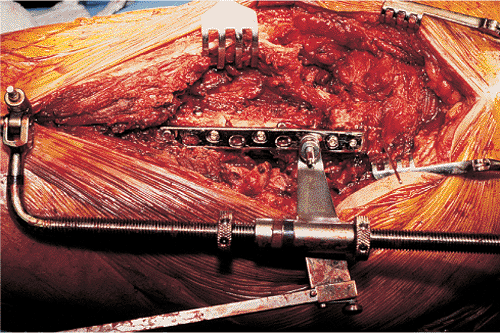
until the fracture fragments are slightly overdistracted (Fig. 19.12).
As the tension in the soft tissue increases, there is a tendency for
the fracture site to deform into varus, resulting in the plate pulling
away from the distal shaft fragment. This can be minimized by placing
several plate-holding clamps to keep the plate reduced to the shaft
cortex as the fracture is distracted (see Fig. 19.12).
butterfly-fracture fragments should be reduced to either the proximal
or distal main fragment prior to insertion of the implant.
Occasionally,
posteromedial fracture fragments involving the lesser trochanter cannot
be reduced until the main fragments have been reduced. These large
fracture fragments are stabilized by lag screws positioned to avoid
interference with the final position of the implant. The distractor
allows manipulation of rotation and correction of angular mal-alignment
during distraction of the fracture. Once alignment of the fracture is
achieved, the distractor is reversed to allow the fracture fragments to
return to an anatomic position (Fig. 19.13).
Lag screws can be inserted between the two main fragments as the
distractor and bone clamps maintain the reduction. The completion of
osteosynthesis is achieved by final screw placement in the plate and
removal of the clamps and distractor. The locking plate allows
compression screws to be used in the distal combination holes to
stabilize simple fracture patterns rigidly. Finally, the hip is
examined under fluoroscopy to assess the reduction and fixation in both
the AP and lateral planes.
 |
|
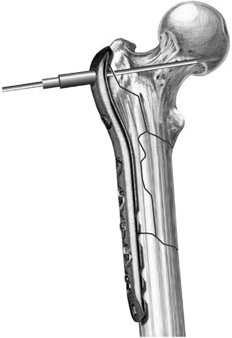
Figure 19.10.
Through a threaded wire guide attached to the most proximal hole (95 degrees), a guide wire is inserted so it lies 1 cm inferior to the piriformis fossa and inferior in the femoral head. It should be central on a lateral view. |
 |
|
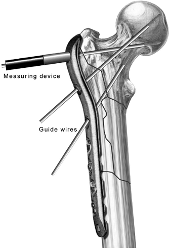
Figure 19.11.
The appropriate screw lengths are measured using an indirect measuring device over the guide wires with the guides still attached to the plate. |
 |
|
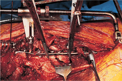
Figure 19.12.
Application of the femoral distractor across the subtrochanteric fracture with bone clamps holding the plate to the distal shaft fragment. Slight overdistraction of 5 mm is performed to allow alignment of major fracture lines. |
comminuted fractures, realignment is achieved by returning the
soft-tissue tension to normal through the use of the distractor and
fluoroscopic evaluation of the overall reduction. Indirect reduction
demands preservation of fracture hematoma by avoiding direct dissection
at the fracture site, and no attempt at interfragmentary compression
with lag screws is performed when there are small comminuted fragments (Fig. 19.14).
Considerable operative skill is required to estimate accurately the
correct fracture length and alignment and the appropriate level of
soft-tissue tension. Locking plates are ideal for use in these
fractures, and the combination holes should be used in locking mode
with 4.5-mm screws placed to bridge the fracture site (Fig. 19.15).
Radiographs are obtained to verify correct length and overall
reduction. Wounds are closed over suction drains. Closure of the vastus
lateralis and tensor fascia lata completes the deep closure, and a
compressive dressing is applied to the wound.
drainage is less than 30 cc over a 24-hour period. Postoperative
prophylactic antibiotics are discontinued when the drains are removed.
Range-of-motion exercises are initiated immediately in the
postoperative period by using a continuous passive-motion machine.
Early mobilization with crutches or a walker is prescribed with only
touchdown weight bearing maintained for the first 6 postoperative
weeks. Thromboprophylaxis, including pulsatile stockings and
anticoagulant therapy, is continued until the patient is able to
ambulate independently, usually within 4 to 5 days after surgery.
Subcutaneous low-molecular-weight heparin or warfarin therapy is
prescribed at the physician’s discretion. Radiographs are obtained at
monthly intervals and
progressive weight bearing is initiated when the radiographs demonstrate callus formation and fracture line healing (Fig. 19.16).
Full weight bearing is usually not possible until 12 weeks after a
subtrochanteric fracture. Patients may return to further activities
once radiographs demonstrate complete fracture healing. Participation
in high-risk contact sports is limited for 6 months after surgery. If
the mechanical axis, extremity rotation, and length are anatomic, the
patient can anticipate an excellent result.
 |
|
Figure 19.13.
Reverse of the overdistraction and settling of the major fracture lines. Once this reduction is achieved, definitive lag-screw fixation is performed between major bone fragments to enhance fixation. |
 |
|
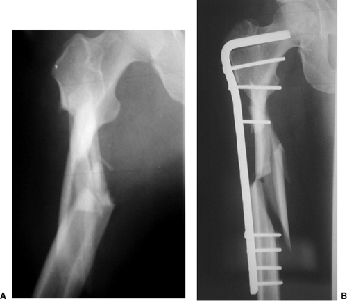
Figure 19.14. A. A comminuted subtrochanteric fracture is best treated with (B) indirect reduction techniques and plate fixation that spans the comminution.
|
subtrochanteric femur fractures varies according to experience of the
surgeon and complexity of the fracture (1,4,10,11,18). Direct reduction, with extensive medial dissection and bone grafting has been associated with poor results (16). Kinast et al (4)
studied two groups of patients with subtrochanteric femur fractures who
underwent either direct or indirect reduction techniques. They found
significantly improved healing time and complication rates for indirect
reduction over those found for direct reduction. High rates of union
and good functional results can be achieved once the technical
difficulties and nuances of the technique are mastered. Because the
surgeon has only one chance to determine the final fracture alignment
apprehension with using blade plates is common. Long-term results
following locked plating are still unknown, but locked screws for
proximal fixation and distal combination holes may offer a theoretical
biomechanical advantage over traditional blade-plate implants.
problems common to any plate device used for treating hip fractures.
Loss of fixation and collapse into varus position can occur with poor
implant placement. When locked screws are used, it is crucial to
visualize all three proximal screws to ensure penetration into the hip
joint has not occurred. The use of these implants in osteoporotic bone
has some risk of failure due to poor purchase. Patients who weight bear
prematurely may produce hardware failure because of
the
high stress concentrations produced in the subtrochanteric area. The
most common complications related to the technique are residual varus
malalignment of the fracture, penetration of the femoral neck with the
blade or screws, external rotation, and shortening of the extremity.
Nonunion rates of up to 16% have been reported (1,4,10,19). Other complications are a direct result of poor insertion technique (including inferior or
posterior penetration of the femoral neck, varus or valgus, internal or
external torsion), and sagittal plane mal-alignment may occur if
attention to the insertion technique is not vigorously observed.
 |
|
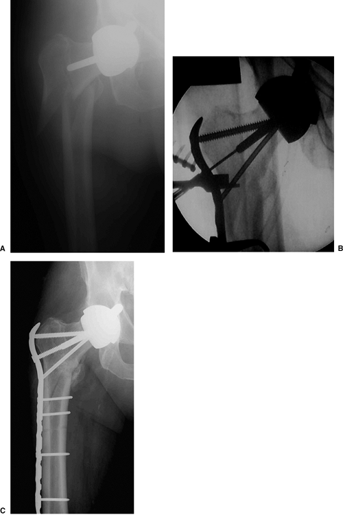
Figure 19.15. A. Example of a locking plate for the treatment of a comminuted subtrochanteric fracture around a femoral head prosthesis. B.
The three proximal guide wires and screws are placed proximally, and the bone is reduced to the plate. An indirect reduction technique was employed in this case, followed by well-spaced locking screws along the shaft of the plate distally. C. X-rays at 3 months show maintained anatomic alignment of the fracture and evidence of healing. |
 |
|
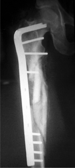
Figure 19.16. Anatomic alignment and healing of a comminuted subtrochanteric fracture.
|
C, Bolhofner BR, Mast JW, et al. Subtrochanteric fractures of the
femur: results of treatment with the 95 degrees condylar blade-plate. Clin Orthop 1989:122–130.
DW, Acevedo JI, Ganey TM, et al. Mechanical comparison of plates used
in the treatment of unstable subtrochanteric femur fractures. J Orthop Trauma 1999;13:534–538.
K, Ceder L, Tidermark J, et al. Extramedullary fixation of 107
subtrochanteric fractures: a randomized multicenter trial of the Medoff
sliding plate versus 3 other screw-plate systems. Acta Orthop Scand 1999;70:459–466.
KA, Muller U, Ganz R. Indirect reduction with a condylar blade plate
for osteosynthesis of subtrochanteric femoral fractures. Injury 1998;29:7–15.
JR, Garland DE, Whitecloud T III, et al. Subtrochanteric fractures of
the femur: treatment with ASIF blade plate fixation. South Med J 1978;71:1372–1375.
SV, Dholakia DB, Chatterjee A. The use of a dynamic condylar screw and
biological reduction techniques for subtrochanteric femur fracture. Injury 2003;34:123–128.
F, Gruber G, Schippinger G, et al. Minimal-invasive treatment of distal
femoral fractures with the LISS (Less Invasive Stabilization System): a
prospective study of 30 fractures with a follow up of 20 months. Acta Orthop Scand 2004;75:56–60.
WW, Wiss DA, Becker V Jr, et al. Subtrochanteric femur fractures: a
comparison of the Zickel nail, 95 degrees blade plate, and interlocking
nail. J Orthop Trauma 1991;5:458–564.