
-
Conventional radiology
-
Contrast arthrography
-
Contrast computed arthrotomography
-
Ultrasonography
-
Magnetic resonance (MR) imaging
high-end equipment used by an experienced examiner.13 In addition, the individual tendons of the rotator cuff are poorly delineated, and as a result a comprehensive assessment of the shoulder is not provided. In our review of 100 consecutive requests for imaging evaluation to rule out rotator cuff tears, almost half the patients had non–cuff-related pathology.12 The majority of non-cuff pathology was caused by labral tears, a condition not easily identified on ultrasound studies. Although conflicting results have been reported for the usefulness of ultrasonography in differentiating partial- and full-thickness tears,9,11,14,15 our direct comparison of MR imaging and ultrasound in both cadavers and patients showed ultrasound to be grossly inadequate in identifying labral tears and paralabral cysts.
in addition to GRE T2*-weighted images. Contrast enhancement with intra-articular gadolinium diethylenetriamine pentaacetic acid (Gd-DTPA) may increase diagnostic conspicuity in partial articular surface tears of the rotator cuff, helps distinguish severe tendinitis from rotator cuff tears, and improves visualization of the capsulolabral anatomy of the glenohumeral joint.16,26,29,31 T1-weighted Gd-DTPA images also minimize the effect of magnetic susceptibility seen with GRE images in the postoperative cuff. With or without gadolinium enhancement, MR arthrography is not required for routine studies when there is access to phased-array shoulder coils and appropriate imaging sequences are used.
 |
|
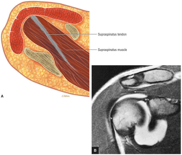
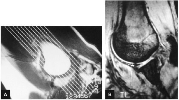
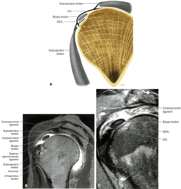
FIGURE 8.1 ● (A) Axial cross-sectional illustration showing a steeper (greater slope) obliquity of the supraspinatus tendon relative to the supraspinatus muscle. Coronal oblique MR images are correctly prescribed using image locations parallel to the supraspinatus tendon. Images improperly obtained parallel to the supraspinatus muscle and not the tendon will foreshorten the supraspinatus tendon in the coronal plane and lead to a potential misdiagnosis of a rotator cuff tear. (B) A T1-weighted coronal oblique MR arthrogram shows the continuity between the supraspinatus muscle and tendon (long white arrow), biceps labral complex (BLC), biceps tendon (b), and coracoacromial ligament (small white arrow).
|
-
Position arm in partial external rotation.
-
Coronal oblique images are performed parallel to the course of the supraspinatus tendon.
-
FS PD FSE coronal oblique images are sensitive to rotator cuff degeneration and fluid signal, and T2 FSE coronal images are required to distinguish between tendinosis and tear.
-
Axial FS PD FSE images are sensitive for the detection of small paralabral cysts as markers for labral tears.
-
Rotator cuff tears should be measured in the coronal and sagittal planes.
-
The glenoid fossa is evaluated in the sagittal plane for patterns of glenoid rim and fossa sclerosis associated with instability and osteoarthritis.
-
ABER (abduction external rotation) images in conjunction with MR arthrography are helpful in evaluating the postoperative labrum and nondisplaced (e.g., Perthes) labral tears.
-
A combination of FS PD-weighted FSE and T2-weighted (without FS) FSE sequences (Fig. 8.2), at 3- to 4-mm slice thickness, with a 256 to 512 (frequency) × 256 (phase) imaging matrix and a 12- to 14-cm field of view (FOV)33
-
A conventional spin-echo sequence with PD and T2-weighted contrast (although this protocol can be used to evaluate the rotator cuff, increased imaging times limit its usefulness)
-
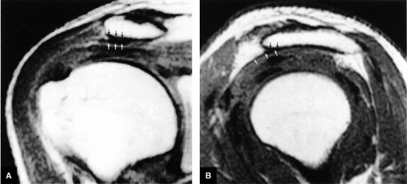
FS PD-weighted FSE scans (these images are more sensitive to subacromial bursal fluid, periarticular fluid, and rotator cuff tendinosis compared to non-FS T2-weighted FSE or conventional T2-weighted images)
-
Non-FS coronal oblique images (recommended to complement the FSE PD FSE sequence)
-
T2 FSE contrast images (these images improve specificity for distinguishing between tendinosis and partial rotator cuff tears)
matrix and longer echo time (TE) values. To maximize signal-to-noise in FS PD-weighted FSE images, TE values are usually between 40 and 50 msec and repetition times (TRs) are between 3000 and 4000 msec. These parameters provide adequate coverage and maximum signal-to-noise. We do not use T2*-weighted coronal oblique images to evaluate the rotator cuff. Although GRE techniques adequately demonstrate bursal and articular cuff outlines, areas of increased signal intensity may be seen in both cuff degeneration and tears, making the distinction between tendinopathy or tendinosis and rotator cuff tear difficult. T2*-weighted axial images are, however, used to evaluate the glenohumeral capsule and labrum, at a FOV of 10 cm. GRE techniques provide good visualization of intralabral degeneration and tears, whereas FS PD FSE images are more sensitive to paralabral cysts and the articular cartilage labral interface. Magnetic susceptibility artifacts (signal void) are prominent with GRE techniques, especially when evaluating the postoperative shoulder. This susceptibility may be useful in identifying loose bodies or foci of calcific tendinitis. Coronal plane images are also used to quantify the medial-to-lateral dimension of a rotator cuff tear.
 |
|
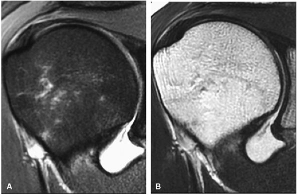
FIGURE 8.2 ● Rotator cuff tendon on coronal FS PD FSE (A) and T2 FSE (B) images using an eight-channel phased-array coil.
|
-
T2* GRE images (10-cm FOV) are used to evaluate intralabral pathology, subscapularis tendinosis, and calcific tendinitis (Fig. 8.3).
-
A separate FS PD-weighted FSE sequence is used to increase sensitivity to fluid and to identify paralabral cysts, articular cartilage labral avulsions, and muscle edema (Fig. 8.4). FSE sequences are less sensitive to intralabral signal intensity in the spectrum of degenerations or tears unless there is imbibed fluid. FSE (FS PD FSE) images, however, are superior for the demonstration of labral morphology in cases of avulsions or contour abnormalities.
without a FS PD FSE sequence to improve sensitivity for fluid and subtle labral tearing at the glenoid rim attachment.
 |
|
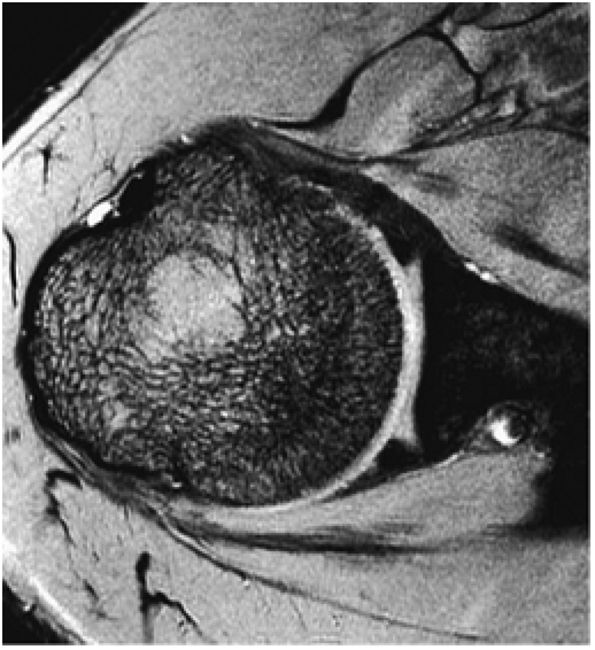
FIGURE 8.3 ● Glenohumeral joint contrast on axial T2* GRE image. Axial GRE images optimize visualization of intralabral signal and subscapularis tendinosis. FS FSE images are more sensitive to fluid collections, paralabral cysts, and articular cartilage.
|
 |
|
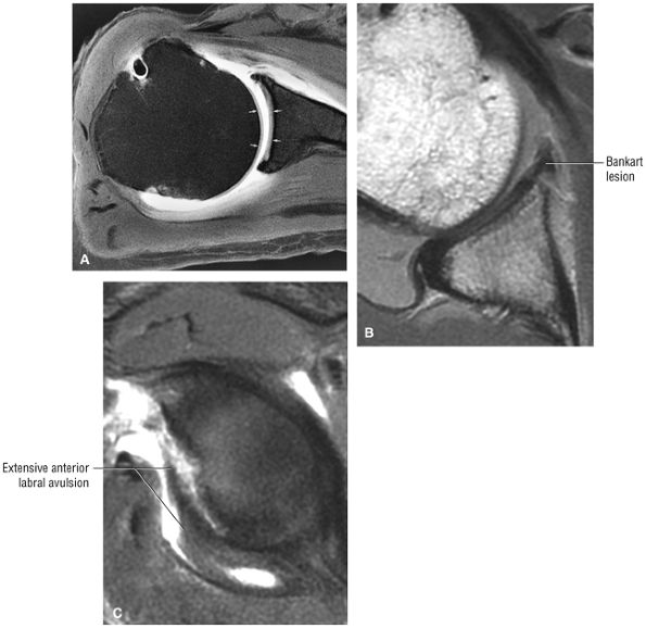
FIGURE 8.4 ● (A) Axial FS PD FSE image shows intact and congruous humeral head and glenoid articular cartilage surfaces (arrows), separate from the high-signal-intensity intra-articular contrast. (B) PD FSE contrast without FS is shown in an axial image of a Bankart lesion. Chondral surfaces are not as well demonstrated. (C) Excellent contrast is shown between the avulsed anterior labrum and the anterior glenoid rim on the corresponding sagittal FS PD FSE image.
|
-
Joint distention, outlining intra-articular structures such as the labrum and capsular ligaments
-
Improved detection of rotator cuff tears, including partial tears
-
Demonstration of communication between the joint and extra-articular abnormalities (e.g., paralabral cysts, bursae, and other fluid-containing masses or potential spaces)
 |
|
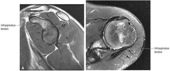
FIGURE 8.5 ● Pseudo-thickening of the infraspinatus tendon resulting from external glenohumeral joint rotation. This is not a cuff tear with retraction. (A) Sagittal PD image. (B) Axial FS PD FSE image.
|
-
The athlete with chronic shoulder pain and an equivocal routine MR examination
-
Postoperative evaluation of repaired labral capsular structures and/or strictures, recurrent rotator cuff tears or partial tears, and displaced hardware
-
The patient with chronic shoulder pain and negative routine MR examination
-
A bursal surface tear or intrasubstance degenerative cuff changes
-
A paralabral cyst that does not directly communicate with the joint (on T2* axial images) and may not be appreciated on post–intra-articular paramagnetic contrast injection FS T1-weighted images
-
Preexisting fluid secondary to an effusion or hemorrhage
 |
|
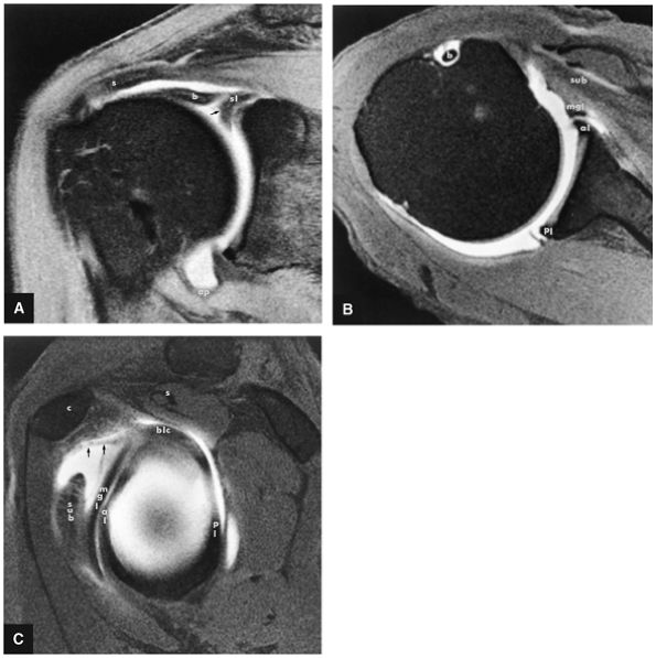
FIGURE 8.6 ● Routine MR arthrography with FS T1-weighted (A) coronal oblique, (B) axial, and (C) sagittal oblique (at the level of the glenohumeral joint) images. s, supraspinatus tendon; b, biceps tendon; SL, superior labrum; arrow, conjoined origin of the superior and middle glenohumeral ligaments; AP, axillary pouch; al, anterior labrum; PL, posterior labrum; MGL, middle glenohumeral ligament; sub, subscapularis tendon; c, coracoid; BLC, biceps labral complex; small arrows, superior glenohumeral ligament.
|
-
FS T1-weighted coronal images (to distinguish contrast from subacromial subdeltoid fat in full-thickness rotator cuff tears)
-
PD-weighted sagittal images, including the medial aspect of the shoulder (to evaluate the belly of the supraspinatus for atrophy and osseous acromion outlet morphology)
-
FS PD FSE sagittal images (to assess the AC joint and intraarticular biceps abnormalities)
-
FS T1-weighted axial images (for high-resolution labral evaluation)
-
FS PD FSE axial images (for labral and glenoid articular cartilage evaluation)
-
PD FSE abduction external rotation (ABER) oblique sagittal images (to evaluate the anterior labrum, the undersurface of the rotator cuff, and the position of the humeral head)
of the brachial plexus (from either soft tissue or osseous encroachment) or secondary increased signal intensity from an area of trauma.
 |
|
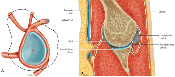
FIGURE 8.7 ● (A) Normal central point (red cross) of glenohumeral rotation with arm positioned in abduction and external rotation. This position of function is achieved by placing the hand behind the head with the patient in the supine position. (B) Axial oblique ABER (abduction and external rotation) anatomy illustrated at the level of the IGHL labral complex posterior to the ABER section through the supraspinatus tendon. The MGHL and conjoined rotator cuff tendon are visualized superior to this section, whereas the inferior labrum and teres minor tendon are demonstrated inferior to this section in the ABER sequence.
|
 |
|
FIGURE 8.8 ● Functional anatomy of the inferior glenohumeral ligament (IGL). (A) A coronal localizer obtained with the arm placed in 90° of abduction (i.e., the position of function of the IGL) and external rotation. (B) The corresponding axial image through the glenohumeral joint shows a taut IGL (small straight arrows) and intact anterior labrum (curved arrow).
|
 |
|
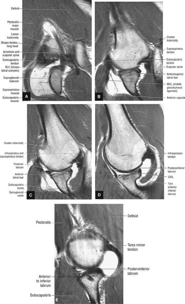
FIGURE 8.9 ● ABER MR arthrogram showing sequential images from superior to inferior. (A) Superior axial oblique image at the level of the biceps labral complex and the long head of the biceps tendon. (B) Anterosuperior axial oblique image at the level of the subscapularis tendon and supraspinatus footprint. (C) Mid-axial oblique image at the level of the conjoined insertion of the supraspinatus and infraspinatus tendons and the spinoglenoid notch. (D) Anteroinferior axial oblique image at he level of the IGL and infraspinatus tendon. (E) Inferior axial oblique image at the level of the inferior labrum and teres minor tendon.
|
-
On anterior and midcoronal oblique images, the supraspinatus muscle and its central tendon are seen in continuity. The low-density supraspinatus tendon is defined at its insertion on the greater tuberosity. The subacromial bursa is interposed between the rotator cuff and the acromion. A fibrofatty layer lies between the acromion, the AC joint, and the superior bursal layer.
-
On anterior coronal images, the subscapularis muscle fibers and multitendinous fibers can be identified where they converge on the lesser tuberosity. Anterior coronal oblique images display the coracohumeral and coracoacromial ligaments as thin black structures.
-
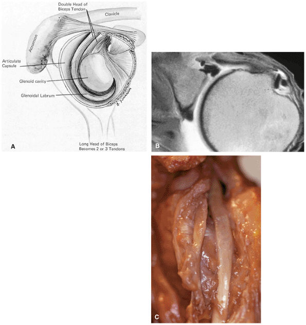
In a neutral position and with internal rotation of the humeral head, the long head of the biceps tendon is seen in the bicipital groove on anterior coronal oblique images. The long head of the biceps tendon enters the capsule inferior to the supraspinatus tendon and can be traced to its insertion on the superior rim of the glenoid at the biceps labral complex (BLC).
-
The coracoclavicular ligaments are also displayed on anterior coronal oblique images. The anatomy of the AC articulation is best displayed at the level of the supraspinatus tendon. When present, AC joint fluid may represent an asymptomatic manifestation of osteoarthritis.41
-
The inferior glenoid labrum and axillary pouch are clearly demonstrated on these oblique images. Subscapularis bursal fluid may extend inferior and medial to the inferior glenoid on anterior coronal images.
-
On midcoronal images, the muscle belly of the supraspinatus extends laterally beyond the glenoid before its central tendon reaches the musculotendinous junction of the rotator cuff. The axillary pouch of the IGHL, with its attachment to the anatomic neck of the humerus and the inferior pole of the glenoid, can also be seen on these images. It is not unusual to see variable
P.1142P.1143P.1144P.1145P.1146P.1147P.1148P.1149P.1150P.1151P.1152P.1153P.1154P.1155P.1156P.1157P.1158P.1159P.1160P.1161P.1162P.1163P.1164P.1165P.1166
amounts of fluid in the axillary pouch in the presence of a joint effusion. Otherwise, the axillary pouch is collapsed. The presence of a glenohumeral joint effusion is associated with osteoarthritis and rotator cuff disease.42 The axillary pouch can be followed from anterior to posterior on coronal oblique images through the shoulder. -
On midcoronal to posterior coronal sections, there is a subtle transition between the supraspinatus and the conjoined insertion of the infraspinatus tendon. Posterior to the AC joint, the supraspinatus tendon forms a conjoined attachment to the greater tuberosity with the infraspinatus tendon. On more posterior sections, the infraspinatus tendon may be mistaken for the supraspinatus tendon, which may be out of the plane of section. Humeral head articular cartilage, intermediate in signal intensity on T1-weighted images, is interposed between the low-signal-intensity supraspinatus tendon superiorly and the cortex inferiorly. The posterior circumflex humeral artery and the axillary nerve are identified medial to the coracobrachialis, the latissimus dorsi, and the teres major muscles and tendons.
-
The teres minor muscles and tendons are shown on more posterior coronal oblique images at the level of the scapular spine, where the teres minor attaches to the greater tuberosity.
 |
|
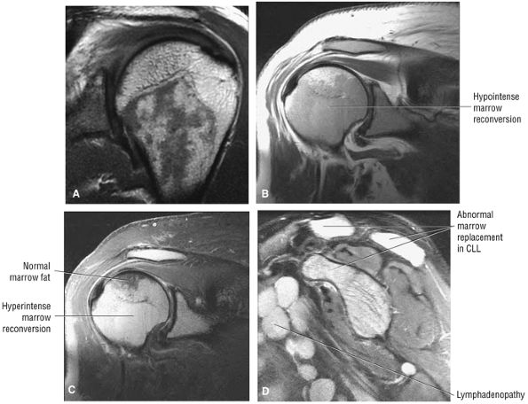
FIGURE 8.10 ● (A) Coronal PD FSE image showing normal hypointense red marrow signal distal to the proximal humeral physeal scar. Red marrow may partially exist in subchondral locations of the proximal humeral epiphysis, providing characteristic T1 and T2 signal intensities. (B, C) Marrow reconversion in polycythemia vera, a myeloproliferative disorder. Red marrow signal intensity is apparent proximal to the physeal scar. Red marrow demonstrates lower signal intensity than fat on coronal PD-weighted images (B) and is hyperintense relative to fat signal on coronal FS PD FSE images. (C). Red marrow associated with pathologic conditions tends to image with greater hyperintensity than normal areas of persistent red marrow. (D) Abnormal hyperintense marrow replacement in chronic lymphocytic leukemia (CLL) on a sagittal FS PD FSE image. CLL is not associated with high-dose radiation or benzene exposure.
|
 |
|
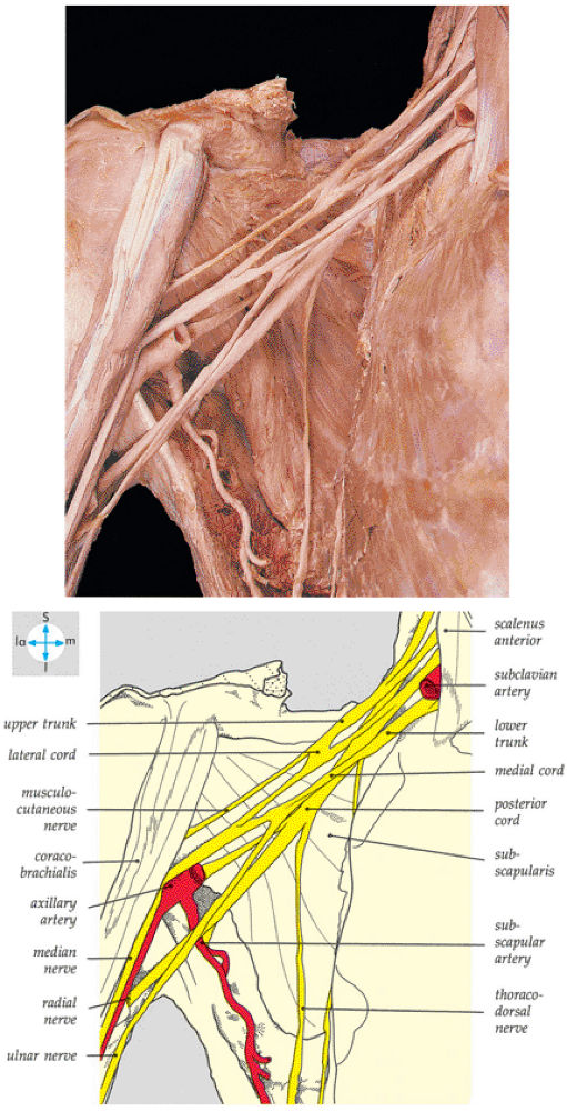
FIGURE 8.11 ● The components of the brachial plexus. The veins and most of the axillary artery have been removed.
|
 |
|
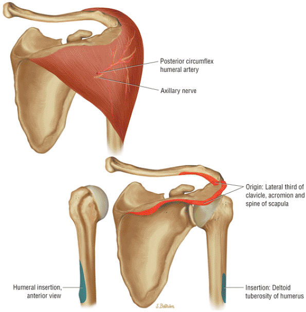
FIGURE 8.12 DELTOID ● The deltoid abducts the arm and represents the largest of the glenohumeral muscles. The deltoid is multipennate, with an anterolateral raphe, and is important in any form of arm elevation. It is active throughout the entire arc of glenohumeral abduction, even if the supraspinatus muscle is inactive.
|
 |
|
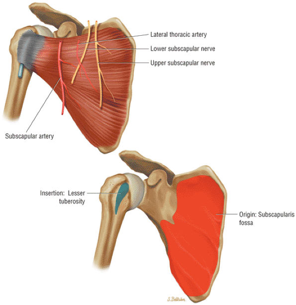
FIGURE 8.13 Subscapularis ● The subscapularis muscle represents the anterior compartment of the rotator cuff. It internally rotates and flexes the humerus. The superior two thirds of the muscle has a tendinous distribution dispersed within the muscle belly, converging into a single large tendon laterally. The inferior third of the subscapularis is muscular throughout its course. The subscapularis forms the upper border of both the quadrilateral and triangular spaces.
|
 |
|
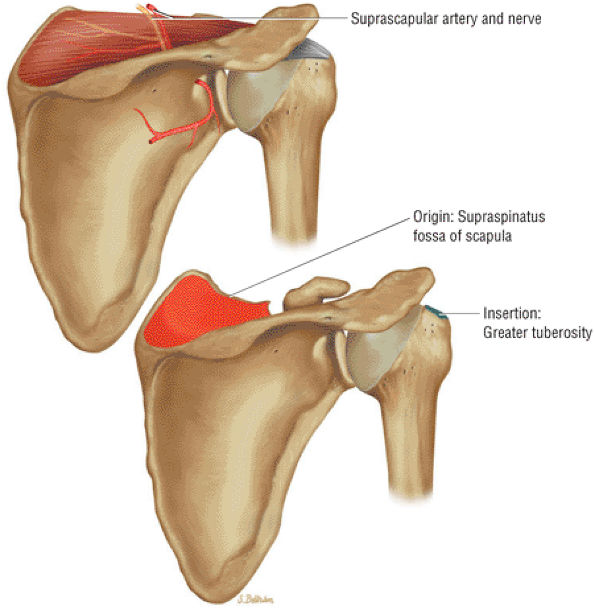
FIGURE 8.14 Supraspinatus ● The supraspinatus initiates abduction of the arm and is active during the entire arc of scapular plane abduction. The parallel independent collagen fascicles permit differential excursion of segments of the tendon. The supraspinatus exerts maximal effort at approximately 30° of abduction and functions with the rotator cuff as a humeral head depressor.
|
 |
|
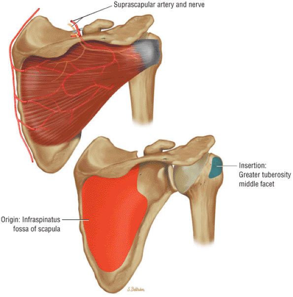
FIGURE 8.15 Infraspinatus ● The infraspinatus functions with the teres minor to externally rotate and extend the humerus. The infraspinatus is more active with the arm in the adducted position and accounts for up to 60% of external rotation force. The infraspinatus contributes to the humeral head depressor action of the rotator cuff.
|
 |
|
FIGURE 8.16 Teres Minor ● The teres minor functions with the infraspinatus to externally rotate and extend the humerus. The teres minor is active with the shoulder in 90° of elevation.
|
 |
|
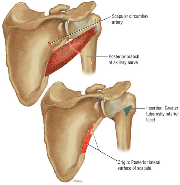
FIGURE 8.17 Teres Major ● The teres major internally rotates and adducts the arm. The axillary nerve and posterior humeral circumflex artery pass superior to the upper border of the teres major through the quadrilateral space. The quadrilateral space is also bordered by the teres minor, the triceps, and the humerus. The teres major functions with the latissimus dorsi muscle in humeral extension, internal rotation, and adduction.
|
 |
|
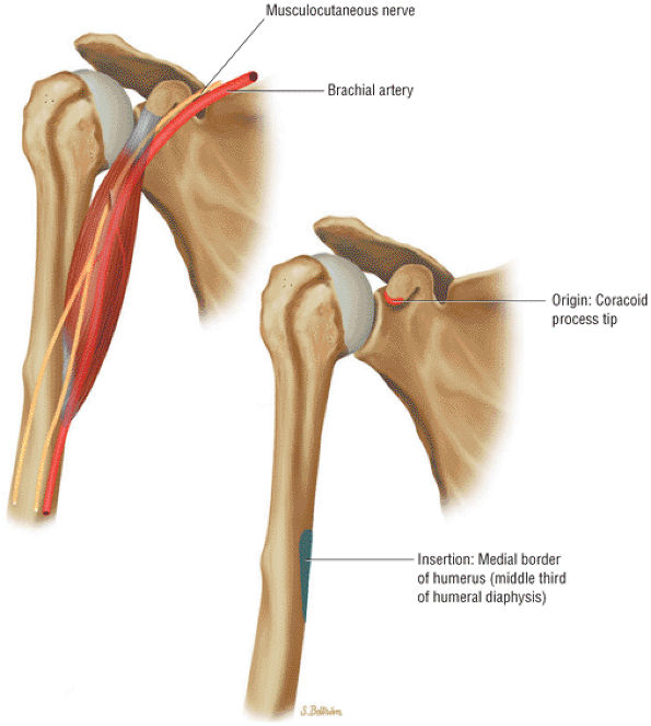
FIGURE 8.18 Coracobrachialis ● The coracobrachialis flexes and adducts the arm. The coracobrachialis and the short head of the biceps have a conjoined tendon origin at the coracoid.
|
 |
|
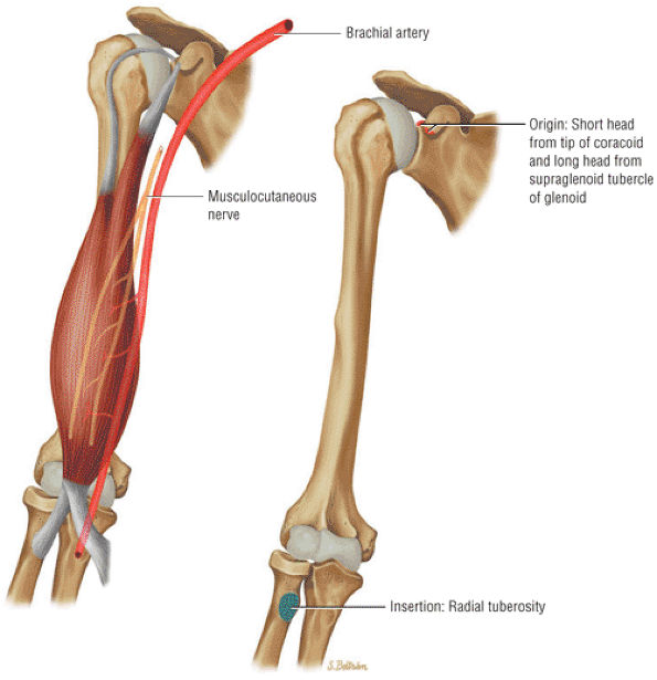
FIGURE 8.19 Biceps Brachii ● The biceps brachii functions to flex and supinate the forearm. The long head of the biceps tendon (LHBT) has origins at both the superior pole of the glenoid and the posterosuperior labrum of the biceps labral complex. The LHBT extends within the synovial sheath of the glenohumeral joint. The long and short head muscle bellies join at the level of the deltoid insertion on the humerus.
|
 |
|
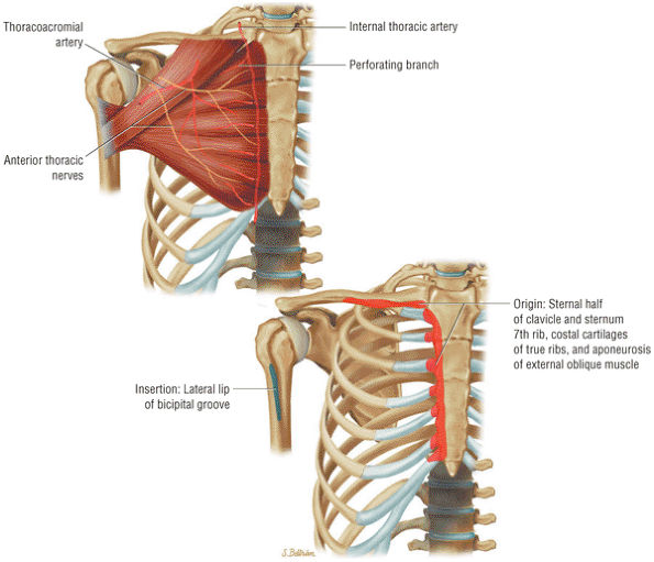
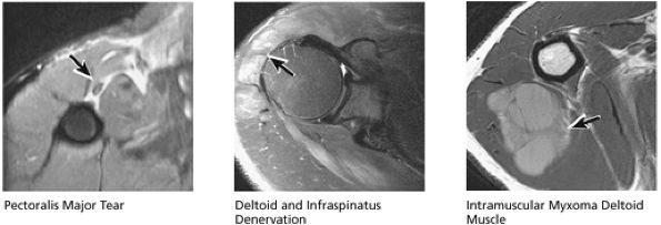
FIGURE 8.20 Pectoralis Major ● The pectoralis major muscle adducts the arm and internally rotates the humerus. The pectoralis major has an upper clavicular and a lower sternocostal head. The clavicular head contributes to the anterior lamina of the broad flat tendon insertion to the humerus, whereas the more distal and deep sternocostal head fibers form the posterior lamina of the tendinous insertion.
|
 |
|
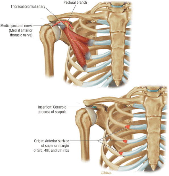
FIGURE 8.21 Pectoralis Minor ● The pectoralis minor and major are internal rotators and flexors of the shoulder joint. The pectoralis minor helps stabilize the scapula.
|
 |
|
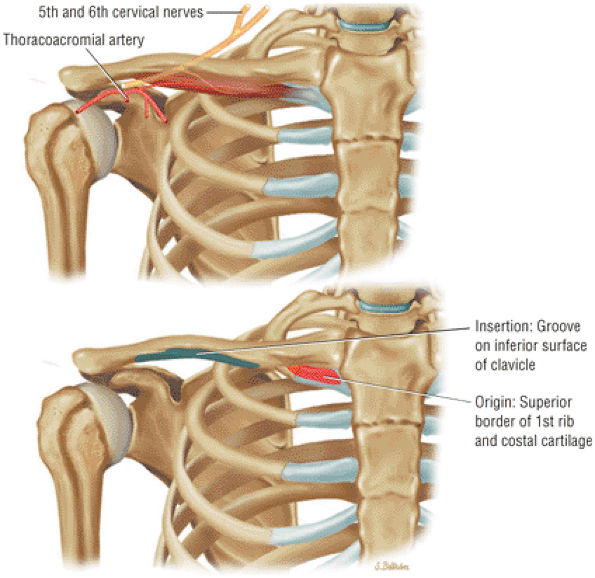
FIGURE 8.22 Subclavius ● The subclavius muscle functions to depress the clavicle.
|
 |
|
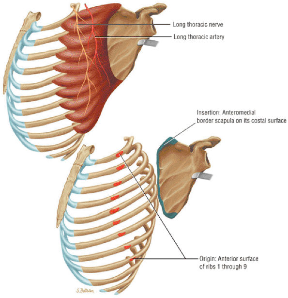
FIGURE 8.23 Serratus Anterior ● The serratus anterior muscle holds the scapula to the chest wall, protracting and allowing for upward rotation. The serratus anterior originates from the outer surface of the first eight or nine ribs. Injury to the long thoracic nerve with absence of serratus function produces a winged scapula with forward flexion of the arm.
|
 |
|
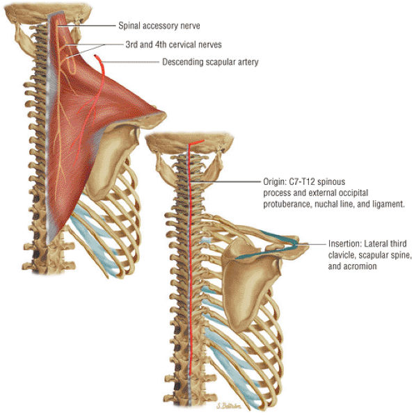
FIGURE 8.24 Trapezius ● The trapezius muscle functions as a scapular retractor by elevating and rotating the scapula.
|
 |
|
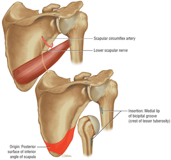
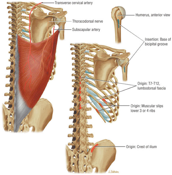
FIGURE 8.25 Latissimus Dorsi ● The latissimus dorsi, which adducts, extends, and internally rotates the humerus, forms the posterior axillary fold. The thoracodorsal nerve arises from the posterior cord and innervates the muscle.
|
 |
|
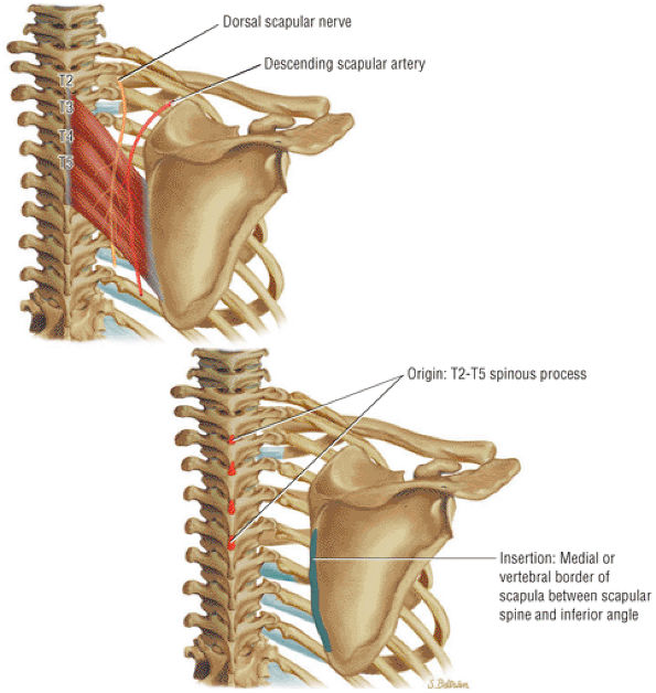
FIGURE 8.26 Rhomboid Major ● The rhomboid major muscle adducts the scapula, participating in its retraction and elevation.
|
 |
|
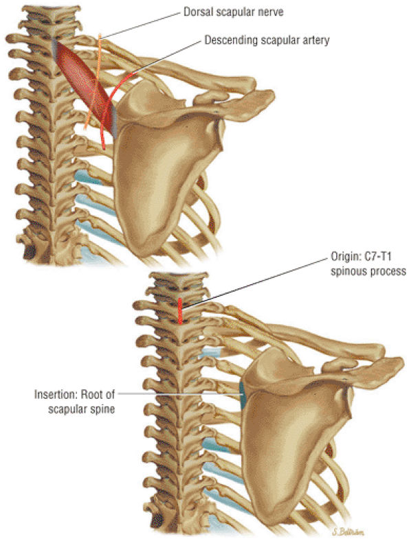
FIGURE 8.27 Rhomboid Minor ● The rhomboid minor and the rhomboid major both retract the scapula and participate in elevation of the scapula.
|
 |
|
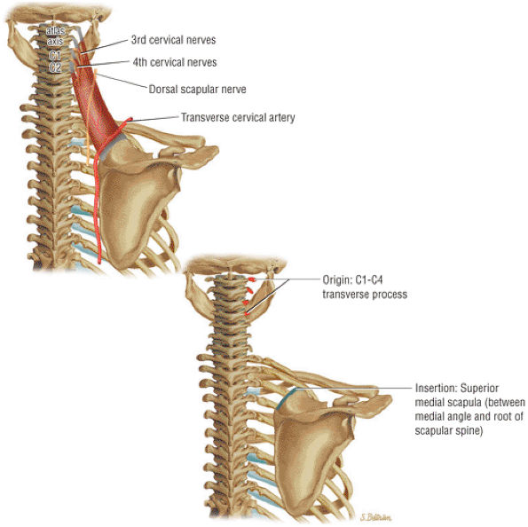
FIGURE 8.28 Levator Scapulae ● The levator scapulae elevates the scapula. In conjunction with the serratus anterior, the levator scapulae produces upward rotation of the scapula. Innervation is from the cervical plexus and occasionally the dorsal scapular nerve. Levator scapulae insertional pain may be caused by a SICK scapula.
|
|
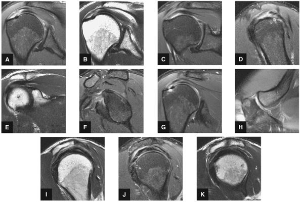
FIGURE 8.29 ● (A) Coronal T1- or PD-weighted images are used to evaluate the distal acromion. (B) Coronal FS PD-weighted images show the majority of the cranial-to-caudal extent of the subscapularis tendon. This image is used to triangulate on subscapularis tears suspected on other planes. Most commonly, tears of the subscapularis begin in the superior articular margin of the tendon. (C) In the setting of supraspinatus tears, coronal T1- or PD-weighted images at or near this image slice are best for assessment of supraspinatus atrophy. (D) Coronal FS PD-weighted images display two important anatomic structures. The first is the anterior-most portion of the distal supraspinatus tendon (also called the “anterior leading edge”), which is seen attaching at the greater tuberosity. This location is the most common starting point for tears of the supraspinatus tendon. The second is the LHBT as it turns 90° around the lesser tuberosity within the proximal portion of the bicipital groove. This is a common location for tendinosis of the biceps tendon. In addition, medial subluxation is visualized in this location, not uncommonly associated with tears of the distal superior supraspinatus tendon. (E) Coronal T1- or PD-weighted images are used to depict the undersurface spurring of the acromion and lateral downsloping of the acromion, both of which are associated with impingement. (F) Coronal FS PD-weighted images show the superior labrum (the anterior superior quadrant). Areas of linear increased signal are normal at this image location, due to fluid/synovium interposed between the multitude of structures coursing toward the superior labrum, including the biceps tendon and the superior glenohumeral ligament. Linear high signal visualized in the labrum is more likely to be due to a tear anterior or posterior to the 12-o—clock position on the glenoid. (I) Coronal T1- or PD-weighted images display the Hill-Sachs lesion, which is visualized as flattening and impaction of the posterior lateral humeral head. This lesion should be differentiated from the extremely common presence of subcortical cystic changes in the posterior lateral humeral head. (J) Coronal FS PD-weighted images are used to display subacromial/subdeltoid fluid. Even in the absence of a rotator cuff tear, fluid in the subacromial/subdeltoid tendon should be described because subacromial/subdeltoid bursitis may mimic the symptoms of a rotator cuff tear and can be a secondary sign of impingement. (K) Coronal T1- or PD-weighted images are used for assessment of infraspinatus muscle atrophy in the setting of rotator cuff tears. This coronal image location is preferred over sagittal plane images because medial retraction of the infraspinatus muscle from a tendon tear can appear falsely atrophic on sagittal images. (L) Coronal FS PD-weighted images demonstrate the insertion of the infraspinatus tendon on the posterior superior portion of the humeral head. Because the insertion is oblique, small tears of the infraspinatus can be difficult to assess in the coronal plane, and infraspinatus pathology in the coronal plane is cross-referenced with sagittal images.
|
-
On superior axial images, the normal oblique course of the supraspinatus muscle is displayed with intermediate signal intensity. The supraspinatus tendon, from its insertion on the capsule and greater tuberosity posterior to the bicipital groove, to the supraspinatus fossa of the scapula, is displayed with low signal intensity. The supraspinatus muscle appears intermediate in signal intensity on T2-weighted and FS PD-weighted FSE images, demonstrating low signal intensity within its tendinous fibers. High-signal-intensity marrow fat is present in the acromion, seen lateral to and parallel with the supraspinatus muscle. In the adducted position, the tendon of the supraspinatus projects lateral to the acromion.
-
At the level of the superior coracoid process, the long axis of the infraspinatus originates from the posteroinferior surface of the scapula, crosses the glenohumeral joint posterior to the supraspinatus, and inserts on the lateral aspect of the greater tuberosity. As it approaches the greater tuberosity posterolaterally, the low-signal-intensity supraspinatus tendon merges with the low-signal-intensity cortex of the humerus. The spine of the scapula separates the supraspinatus and infraspinatus muscles.
-
The teres minor is posterolateral to the infraspinatus, originating at the axillary border of the scapula and inserting on the inferior facet of the greater tuberosity.
-
In cross-section, the tendon of the long head of the biceps is seen as a low-signal-intensity structure within the bicipital groove and is sometimes associated with a small amount of high-signal-intensity fat.
-
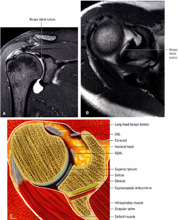
The suprascapular artery and nerve are located posterior and medial to the superior glenoid rim. The dark, low-signal-intensity labrum is located at the level of the glenohumeral articulation, inferior to the coracoid. Normally, the anterior and posterior labrum have well-defined triangular shapes. The posterior labrum may be smaller and more rounded than the anterior labrum. With internal rotation, however, the anterior labrum appears to be larger than the posterior labrum.
-
Glenohumeral articular cartilage follows the concave shape of the glenoid cavity and demonstrates intermediate signal intensity on T1-weighted images and bright signal intensity on T2*-weighted images. Articular cartilage of the glenoid margin of the anterior labrum may be mistaken for a tear. Articular cartilage of the glenohumeral joint is better evaluated on FS PD-weighted FSE sequences.
-
Anteromedial to the glenoid, the subscapularis muscle arises from the subscapularis fossa and inserts on the lesser tuberosity. The low-signal-intensity subscapularis can then be identified anterior to the apex of the anterior glenoid labrum. The subscapularis tendon is present at the level of the middle and superior glenohumeral joint.
-
The MGHL is identified as a low-signal-intensity thin band or cord anterior to the anterior labrum, and the anterior band of the IGHL is between the anterior labrum and the subscapularis tendon. The MGHL may be closely applied to the anterior aspect of the anterior labrum or plastered against the subscapularis tendon, indistinguishable from the low-signal-intensity subscapularis without the benefit of intra-articular contrast. The SGHL is identified at the level of the coracoid and the biceps tendon.
-
With the arm abducted by the patient—s side, axial images through the inferior glenohumeral joint display the IGHL as a lax structure. The axillary pouch of the IGHL is identified inferior to the level of the bony glenoid and requires axial sections that extend inferior to the glenohumeral joint. The subacromial-subdeltoid bursa and the deltoid muscle can be identified between the rotator cuff and the acromion.
-
On midsagittal and lateral sagittal images, the supraspinatus, infraspinatus, and the conjoined cuff tendons demonstrate low signal intensity between the acromion and the superior articular surfaces of the humeral head. The thickened tendon seen in the anterior
P.1167P.1168P.1169P.1170P.1171P.1172P.1173P.1174P.1175P.1176P.1177P.1178P.1179P.1180
half of the sagittal images is the supraspinatus component, whereas the flatter tendon that arches over the posterior half of the humeral head is the infraspinatus component. -
The long head of the biceps tendon is identified anterior and inferior to the supraspinatus tendon on lateral sagittal images and can be followed to its attachment to the BLC at the level of the glenohumeral joint.
-
Toward the glenoid, the coracoacromial ligament is seen as a low-signal-intensity band that arches over the anterior aspect of the rotator cuff from the acromion and coracoid.
-
Medial sagittal sections display the clavicle and AC joint in profile. The oblique transversely oriented physis is also delineated on sagittal images. Marrow inhomogeneity, seen frequently as red-to-yellow marrow conversion, may not be complete distal to the physis in the metadiaphyseal region.43
-
The low-signal-intensity glenoid labrum is also defined on sagittal images that transect the glenohumeral joint. The anterior band of the IGHL can be seen extending anterior and superior to become the anterior labrum. The MGHL is seen anterior to the anterior labrum. The subscapularis tendon is located anterior to the MGHL. This relationship is constant, even though the MGHL may be variable in size and shape. The MGHL may also be absent. The axillary pouch extends between the anterior and posterior bands of the IGHL.
-
Medial sagittal images demonstrate the coracoclavicular ligaments. The low-spin-density tendon of the supraspinatus is identified in the anterior portion of the supraspinatus muscle. The pectoralis minor and coracobrachialis muscles are anterior to the coracoid process. The axillary artery, vein, and brachial plexus are anterior to the subscapularis muscle, deep to the pectoralis minor. The subscapularis muscle and tendon are anterior to the capsule of the glenohumeral joint. The long head of the biceps tendon enters the joint capsule superiorly, anterior and inferior to the supraspinatus tendon. The SGHL lies anterior to the humeral head and glenoid and inferior to the long head of the biceps tendon. The MGHL is anterior to the medial humeral head or lateral glenoid. The thick inferior glenoid labrum is seen as a low-signal-intensity structure along the inferior aspect of the glenoid.
|
FIGURE 8.30 ● Axial images through the AC joint should be obtained on all shoulder MR examinations. (A) Axial T1- or PD-weighted images at this location are used to identify fractures of the distal clavicle and to demonstrate an os acromiale. (B) Axial FS PD-weighted images show cartilage covering the distal aspect of the clavicle and the medial aspect of the acromion at the AC joint. Cartilage defects and thinning, as well as subchondral bone marrow edema and cystic change, are evaluated on axial images through the AC joint. These degenerative changes can mimic the symptoms of a rotator cuff tear. (C) Axial T1- or PD-weighted images demonstrate the Hill-Sachs lesion of the humeral head, usually visualized as focal flattening or concave deformities in the posterolateral humeral head. The Hill-Sachs lesions is identified on the first or second superior axial image through the humeral head. Subcortical cystic change is more commonly visualized in the posterolateral humeral head and is usually an incidental finding in asymptomatic patients. (D) Axial FS PD-weighted images depict the biceps tendon coursing across the anteromedial aspect of the humeral head, within the rotator interval. This image location serves as a starting point for following the remainder of the biceps tendon into the bicipital groove on successive axial images moving from cranial to caudal. Tears of the supraspinatus and infraspinatus tendons are also identified at this image location on axial images. (E) Axial T1- or PD-weighted images allow evaluation of subcoracoid impingement. (F) In this location, thickening and increased signal in the superior glenohumeral ligament and coracohumeral ligament on an axial FS PD-weighted image may indicate adhesive capsulitis, particularly when accompanied by thickening and increased signal within the inferior glenohumeral ligament. (G) Axial T1- or PD-weighted images are used to identify subcortical cystic change in the greater and lesser tuberosity. This finding is commonly an indirect indication of abnormality or tearing in the overlying distal supraspinatus and subscapularis tendons, respectively. (H) Axial FS PD-weighted images through the proximal bicipital groove are used to identify “hidden lesions,” which are diagnosed when the biceps tendon is medially subluxing out of the bicipital groove, usually into a distal subscapularis tear or anterior to the lesser tuberosity. A degenerated biceps tendon may appear flattened and elongated as it rounds the lesser tuberosity into the proximal bicipital groove. Commonly, only the medial “tail” of the flattened degenerated biceps tendon subluxes out of the groove; the remainder of the flattened biceps tendon stays within the groove. (I) Axial T1- or PD-weighted images display the osseous glenoid subchondral surface, which should appear flat. Osseous glenoid remodeling, hypertrophy, deformity, subchondral cystic change, and edema are commonly identified as indirect evidence of overlying chronic cartilage degeneration or prior trauma. Posterior glenoid spurring may completely replace a degenerated or markedly attenuated posterior labrum. (J) Axial FS PD-weighted images are optimal for displaying the glenoid and humeral head cartilage. Chondral fissures, thinning, and defects are visualized when viewing successive cranial-to-caudal images through the glenohumeral joint. The anterior and posterior labrum are also optimally visualized and are normally firmly adherent to the glenoid and glenoid articular cartilage. (K) Axial T1- or PD-weighted images are used to identify bony Bankart lesions. These lesions are seen on inferior axial images through the glenohumeral ligament as oblique fracture lines extending through the anterior inferior glenoid. (L) Axial FS PD-weighted images show the prominent anterior band of the IGHL, which is occasionally mistaken for a tear of the anterior inferior labrum when fluid is interposed between the anterior band and the normal labrum.
|
|
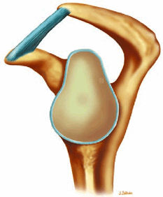
FIGURE 8.31 ● (A) Sagittal T1- or PD-weighted images show the coracoclavicular ligament extending from the anterosuperior aspect of the coracoid process to attach onto the undersurface of the distal clavicle. Sagittal images through the plane of the ligament are optimal for diagnosing coracoclavicular tears or sprains in cases of suspected AC joint separation. (B) Sagittal FS PD-weighted images are used to demonstrate intramuscular ganglion cysts, which are commonly visualized along the myotendinous junction of the supraspinatus and infraspinatus muscles, often at or medial to the level of the glenoid. These ganglion cysts can be followed laterally on successive sagittal images to the level of the distal rotator cuff tendon, where they commonly communicate with partial articular-side tendon tears. These ganglions may be caused by imbibition of joint fluid into the muscle through a partial tendon tear via a one-way check valve at the tear. (C) Sagittal T1- or PD-weighted images are used to assess the shape of the glenoid, which should normally appear somewhat pear-shaped. Chronic erosion of the anterior-inferior glenoid from repetitive trauma may result in an abnormal “inverted-pear” shape, which can predispose to recurrent dislocations. In addition, bony Bankart fractures are diagnosed on the sagittal image through the glenoid as an oblique fracture line extending across the anterior-inferior glenoid. (D) Sagittal FS PD-weighted images through the level of the labrum are useful for confirming labral tears suspected from viewing labral abnormalities in other planes. High signal is often visualized on sagittal images within the labrum or in an arc just superficial to the torn labrum, possibly from perilabral inflammation. Sagittal images are also useful in the identification of associated paralabral cysts and localizing their origin. (E) Sagittal T1- or PD-weighted images medial to or at the level of the glenoid can be used to diagnose rotator cuff muscle atrophy. However, in the setting of a rotator cuff tear with significant retraction, the muscle of interest may be retracted medially, sometimes medial to the sagittal plane that is being used for making the atrophy assessment. Since sagittal plane images used alone may falsely suggest atrophy, confirmation of atrophy should be obtained on the coronal plane images. (F) Sagittal FS PD-weighted images through the glenohumeral joint optimally display the anterior and posterior bands of the IGHL and are useful for confirming adhesive capsulitis, sprains, or tears of the IGHL. Further confirmation of adhesive capsulitis is obtained when the changes of capsular increased signal and thickening involve not only the axillary pouch, but also the joint capsule within the rotator interval, best identified in the sagittal plane. (G) Sagittal T1- or PD-weighted image sectioning through the AC joint. In cases of significant degenerative joint disease, hypertrophic changes, including inferior spurring of the anterior acromion or distal clavicle, are visualized in this location. Inferior spurring pressing into the supraspinatus muscle is associated with impingement and may mimic pain from a rotator cuff tear. (H) Sagittal FS PD-weighted images at this location show the LHBT in cross-section coursing through the rotator interval. Sagittal images are useful in the identification of tendinosis of the biceps tendon within the rotator interval. In the case of complete biceps tendon tear from the biceps labral anchor with distal retraction, the rotator interval appears empty, with no biceps tendon identified. (I) Sagittal T1- or PD-weighted images through the acromion are used for identification of broad-based osteophytic spurring along the undersurface of the acromion from anterior to posterior. Spurring is associated with impingement. (J) Sagittal FS PD-weighted images at this location display tears of the distal subscapularis tendon as high signal within the tendon, most commonly beginning at the superior margin of the tendon. When a tear of the subscapularis is identified, the biceps tendon should be examined for any evidence of medial subluxation into the subscapularis tear. (K) Sagittal T1- or PD-weighted images are used to examine the multiple slips of the deltoid muscle, which fan out from the acromion and clavicle, for strain, tear, or denervation. In patients who have had acromioplasty, the deltoid attachments to the acromion are examined to exclude dehiscence or detachment. (L) Sagittal FS PD-weighted images at this location show the biceps tendon as it turns 90° from the rotator interval to descend vertically within the bicipital groove. This is a common location for biceps tendinosis. (M) Sagittal T1-weighted images are used to evaluate the humeral head physis. In children and adolescent throwing athletes, subtle widening and irregularity may suggest a chronic physeal stress injury, called “Little Leaguer—s shoulder.” (N) Sagittal FS PD-weighted images display the distal supraspinatus, infraspinatus, and teres minor tendons where they insert on the lateral aspect of the humeral head. Sagittal images through the distal tendon insertions can localize tears. The anterior-to-posterior dimension of tendon tears is measured on sagittal images.
|
-
Acromion and acromioclavicular joint
-
Rotator cuff
-
Biceps tendon and pulley
-
Labrum
-
Glenohumeral joint cartilage and osseous structures
-
Capsular ligaments
 |
|
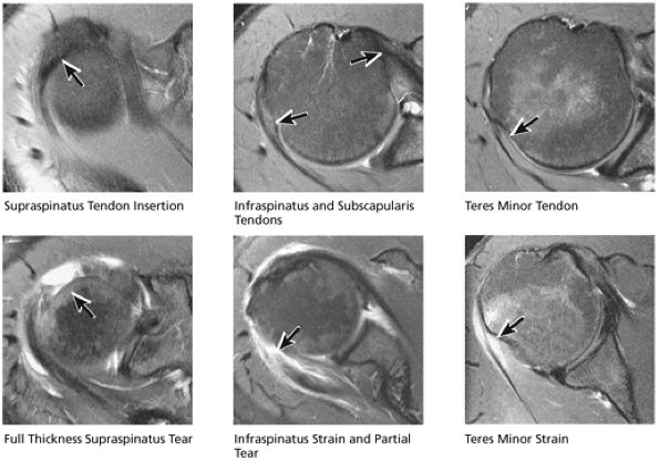
FIGURE 8.32 Rotator Cuff.
|
 |
|
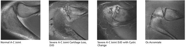
FIGURE 8.33 Acromioclavicular Joint.
|
 |
|
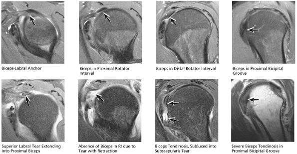
FIGURE 8.34 Biceps Tendon.
|
 |
|
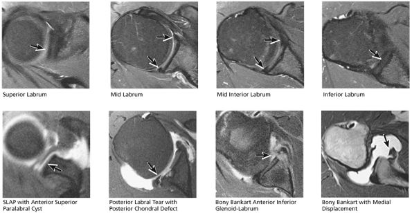
FIGURE 8.35 Labrum.
|
 |
|
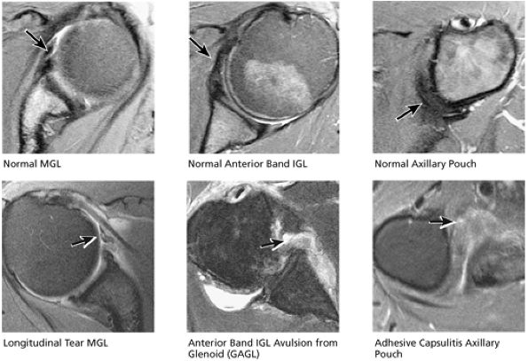
FIGURE 8.36 IGL.
|
 |
|
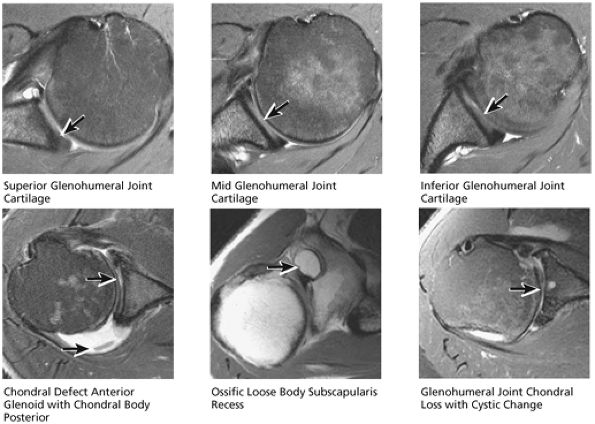
FIGURE 8.37 Glenohumeral Joint.
|
 |
|
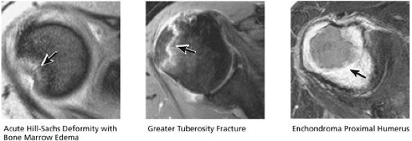
FIGURE 8.38 Osseous.
|
 |
|
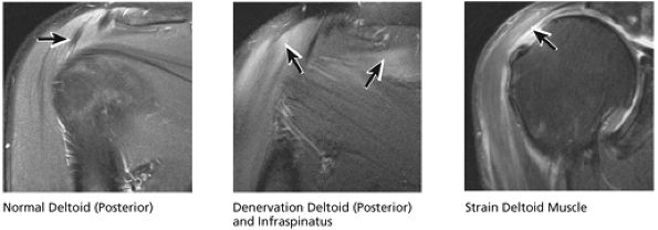
FIGURE 8.39 Deltoid Muscle.
|
stripped from its lesser tuberosity attachment. However, because of an intact connection with the transverse humeral ligament, which connects the subscapularis tendon to the greater tuberosity, the tendon fibers appear to course in continuity without retraction. Proximal biceps tendon and subscapularis tendon pathology commonly coexist, since the pathogenesis of tendinosis and tears of both tendons are interrelated.
 |
|
FIGURE 8.40 Acromioclavicular Joint.
|
 |
|
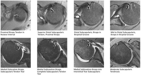
FIGURE 8.41 Subscapularis and Biceps.
|
 |
|
FIGURE 8.42 Labrum.
|
routine shoulder MR examination, when edema and hemorrhage are seen adjacent to the biceps tendon along the proximal humeral shaft. The large arc of muscle bundles making up the deltoid muscle are visualized on axial images anterior, lateral, and posterior to the humeral head and rotator cuff muscles.
 |
|
FIGURE 8.43 Capsule.
|
 |
|
FIGURE 8.44 Glenohumeral Joint Cartilage.
|
 |
|
FIGURE 8.45 Osseous.
|
tendon tears and may result from fluid entering the muscle via a one-way valve mechanism through a partial-thickness tendon tear.
 |
|
FIGURE 8.46 Rotator Cuff.
|
 |
|
FIGURE 8.47 Muscle.
|
 |
|
FIGURE 8.48 Rotator Cuff.
|
and broad-based undersurface spurs that extend along the majority of the acromial undersurface area. Inferior spurring of the distal clavicle from AC joint arthrosis can also narrow the outlet and impress upon the superior surface of the supraspinatus, leading to rotator cuff impingement and pain. Fluid and bursitis in the subacromial/subdeltoid space, often the result of impingement, are also characterized on sagittal images.
 |
|
FIGURE 8.49 AC Joint.
|
 |
|
FIGURE 8.50 Acromion.
|
the bicipital groove. The sagittal plane is useful in identification of tendinosis of the proximal biceps tendon both within the rotator interval and at the proximal bicipital groove. Complete tears with retraction of the biceps tendon into the bicipital groove are displayed as absence of the biceps tendon within the rotator interval.
 |
|
FIGURE 8.51 Biceps Tendon.
|
 |
|
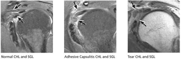
FIGURE 8.52 CHL and SGL.
|
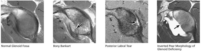
identified. In patients with a history of recurrent dislocations, a sagittal image through the glenoid demonstrates deficiency of the anterior inferior glenoid, manifested as bony Bankart fractures through the anterior inferior glenoid or remodeling and attrition of the anterior inferior glenoid, resulting in an “inverted pear” appearance. Subchondral cystic changes in the glenoid are seen as focal high-signal areas within the glenoid, suggesting overlying chondromalacia.
 |
|
FIGURE 8.53 Glenoid Fossa.
|
 |
|
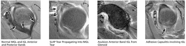
FIGURE 8.54 MGL and IGL.
|
 |
|
FIGURE 8.55 Sample Case.
|
cystic change in the posterior greater tuberosity subjacent to the rotator cuff tear (Fig. 8.55G).
-
Interstitial tear extending from the posterior supraspinatus tendon to the anterior infraspinatus tendon. The anterior margin of the tear extends to the articular surface.
-
Type 2 SLAP tear extending primarily into the posterior superior labrum
-
Anterior inferior acromial spurring, os acromiale, and mild subacromial/subdeltoid bursitis
-
The clavicle connects the axial and appendicular skeletons of the upper extremity.44 It is S-shaped in configuration, with a convex anterior border medially and a concave
P.1195P.1196
anterior border laterally. It is flattened and narrowed laterally and has a thicker cylindrical configuration medially. The clavicle articulates with the sternoclavicular joint medially and with the AC joint laterally (Fig. 8.57). The surfaces of the sternoclavicular joint are covered by fibrocartilage, and a fibrocartilaginous articular disk divides the joint into separate recesses.45 -
The scapula consists of the scapular body, the scapular spine, the scapular neck, the acromion, the glenoid fossa, and the coracoid process.44 The subscapular fossa represents the costal concave surface of the scapula. The dorsal convex surface of the scapula is separated into supraspinous and infraspinous fossae divided by the spine of the scapula. The suprascapular nerve is located in the supraspinous or spinoglenoid notch, at the superior border of the supraspinous fossa. Compression of the suprascapular nerve by a ganglion or entrapment, secondary to thickening of the suprascapular ligament, occurs in this location.
-
The tip of the coracoid projects anterior and lateral to the glenoid, with its origin superior and medial on the scapular neck. The coracoid is an important surgical landmark because neurovascular structures travel along its inferomedial surface.
-
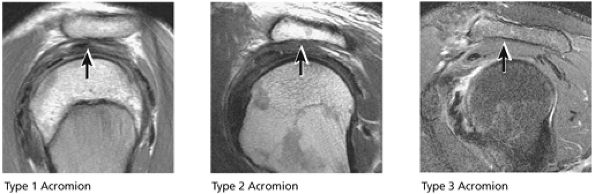
The acromion is classified into several types according to its morphology:
-
Type 1 (a flat or straight undersurface with a high angle of inclination)
-
Type 2 (a curved arc and decreased angle of inclination)
-
Type 3 (hooked anteriorly with a decreased angle of inclination)
-
Type 4 (upward convexity of the inferior surface) (see also the discussion of the etiology of shoulder impingement syndrome)
-
 |
|
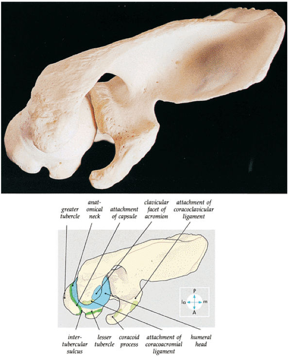
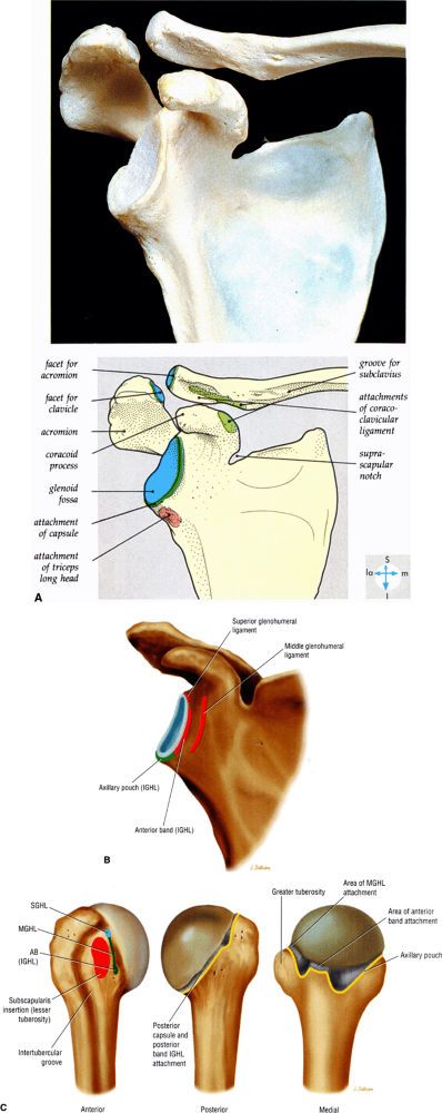
FIGURE 8.56 ● A superior view of the scapula and the upper end of the humerus. The acromion and the coracoacromial ligament prevent upward displacement of the humeral head.
|
 |
|
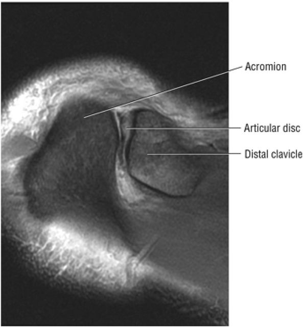
FIGURE 8.57 ● The hypointense articular disc is attached to the capsule and separates the two articular surfaces. Degenerative changes at the disc are associated with fibrillation, degeneration, or erosion of the joint articular cartilage.
|
-
At the lateral angle of the scapula is the glenoid cavity (glenoid fossa) with its supraglenoid and infraglenoid tuberosities. The glenoid version angle varies and may contribute to instability patterns of the shoulder.
-
The proximal humerus consists of the head, anatomic neck, and the greater and lesser tuberosities. The intertubercular or bicipital groove is located between the greater and lesser tuberosities along the anterior surface of the humerus. A decrease in the height of the medial wall of the lesser tuberosity and the presence of a supratubercular ridge of bone projecting from the superolateral aspect of the lesser tuberosity may predispose to instability of the biceps tendon within the groove, but dislocation or subluxation of the biceps tendon is extremely rare in the absence of a massive rotator cuff tear.
-
The BLC is classified as type 1, 2, or 3.
-
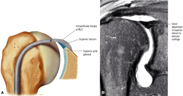
Type 1 BLC has the superior labrum firmly attached to the superior pole of the glenoid.
-
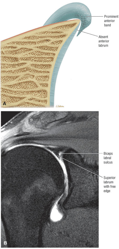
The superior labral sulcus in BLC types 2 and 3 should not be mistaken for the more anterior (anterosuperior quadrant) sublabral foramen (also known as the sublabral hole).
-
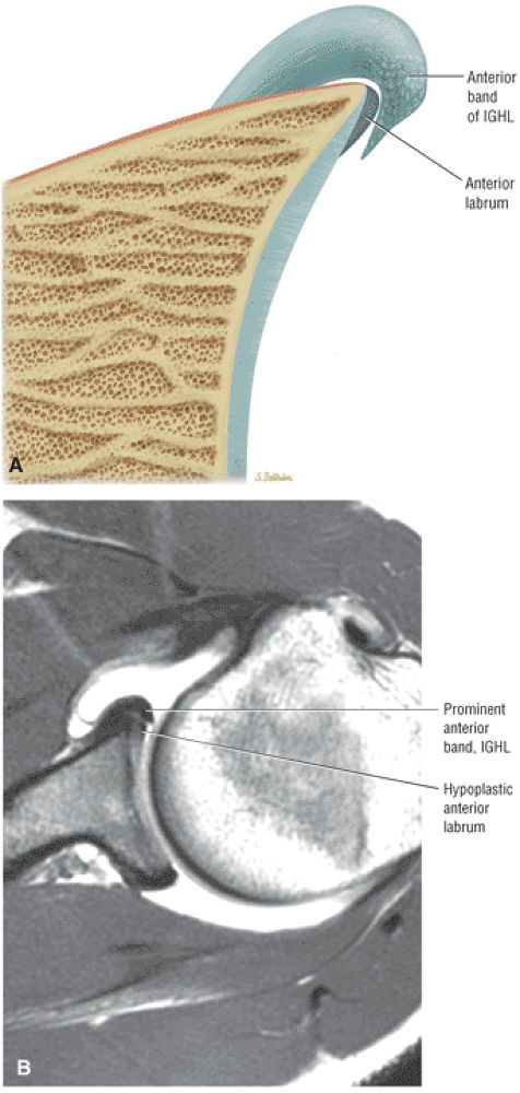
The IGHL contributes to the anterior labrum through its anterior band. The anterior band may be prominent and overlay a small or even absent anterosuperior labrum as a normal variation.
-
The MGHL may be cord-like, absent, thin, or redundant on MR.
-
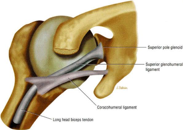
The superior glenohumeral and coracohumeral ligaments stabilize the long head of the biceps tendon by forming the biceps pulley or sling in the rotator cuff interval.
muscle. Glenohumeral joint version or humeral retroversion projects the axis of the humeral head joint surfaces 25° to 40° from the coronal plane, whereas the glenoid surface is retroverted 4° to 12° with respect to the scapula.46 The glenoid labrum, wedge-shaped in cross-section, is a ring of fibrous tissue with transitional fibrocartilage attached to the margin of the glenoid cavity.47 Labral tissue deepens the depression of the glenoid fossa and enlarges the glenohumeral socket contact area (Figs. 8.58 and 8.59).
 |
|
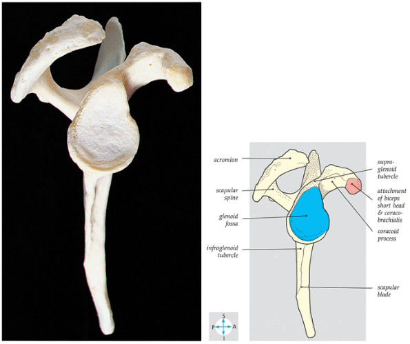
FIGURE 8.58 ● The lateral aspect of the scapula shows the pear-shaped glenoid fossa. The positions of the supraspinatus, infraspinatus, and subscapular fossae are shown.
|
 |
|
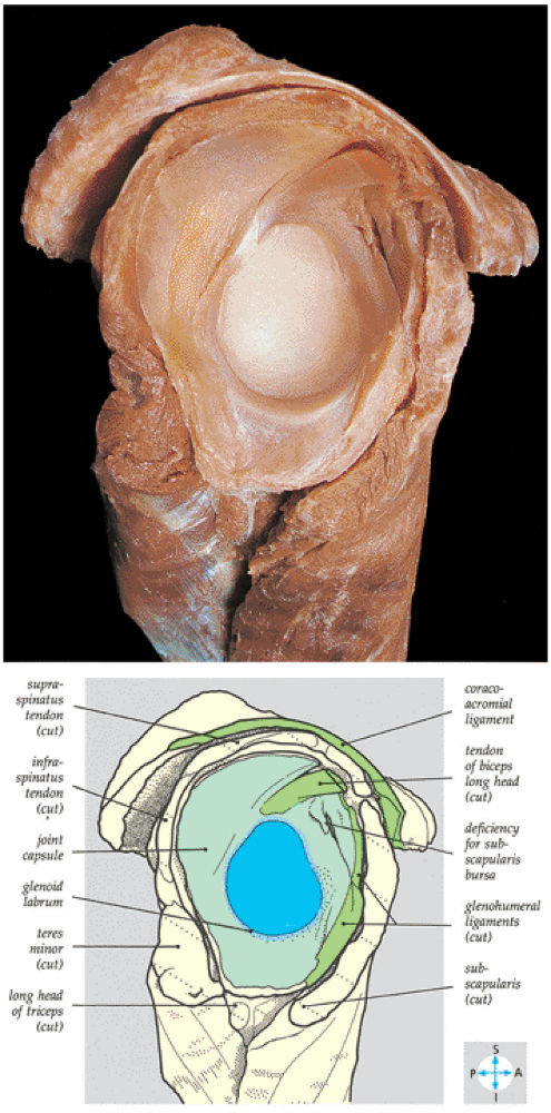
FIGURE 8.59 ● The scapular component of a disarticulated shoulder joint. The relations and internal features of the joint are seen.
|
 |
|
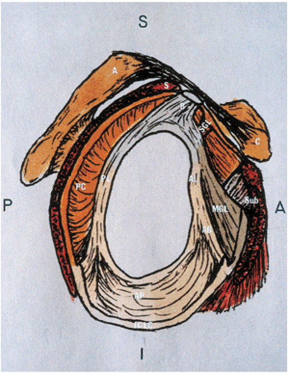
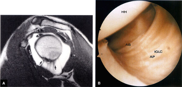
FIGURE 8.60 ● Glenohumeral capsular anatomy. A, acromion; AB, anterior band of IGHL; AL, anterior labrum; AP, axillary pouch of IGHL; B, biceps tendon; C, coracoid; IGLC, IGHL complex; MGL, middle glenohumeral ligament; PC, posterior capsule; PL, posterior labrum; S, supraspinatus tendon; SGL, superior glenohumeral ligament; Sub, subscapularis tendon.
|
 |
|
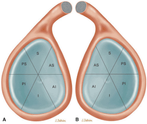
FIGURE 8.61 ● Six quadrants of the glenoid. MR units may default to a display of sagittal images of the shoulder from a left-shoulder perspective even if the right shoulder was imaged. It is accepted practice to describe a lesion by its quadrant. The description of the superior pole as 12 o—clock and the inferior pole as 6 o—clock is accurate for both right and left shoulders. To avoid mistaking right for left, however, use of the 3-o—clock or 9-o—clock positions should be avoided. (A) Illustration using a right-shoulder perspective. (B) Left-shoulder perspective. S, superior; AS, anteroposterior; AI, anteroinferior; I, inferior; PS, posterosuperior; PI, posteroinferior.
|
-
A superior wedge labrum with the labrum firmly attached anteriorly, posteriorly, and inferiorly. Separation (a sublabral foramen) between the glenoid and superior anterior labrum occurs as a normal variation (Fig. 8.62).
-
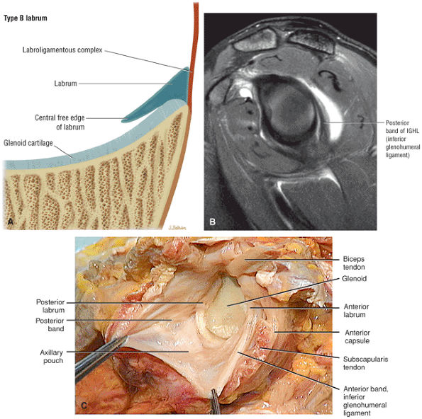
A posterior wedge-shaped labrum in which the superior labrum is smaller and more firmly attached to the superior glenoid. The posterior labrum overlaps the articular surface of the glenoid and has a free central border (Fig. 8.63).
-
An anterior wedge labrum, which is characterized by a large anterior band of the IGHL that replaces or covers a small anterior labrum (e.g., the Buford complex) (Fig. 8.64)
-
A labrum with the characteristics of both a superior and anterior wedge labrum (Fig. 8.65)
-
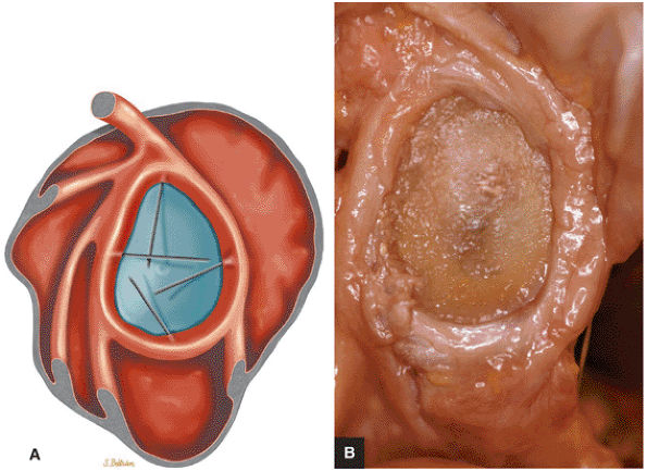
A meniscal or meniscoid labrum, which has a circumferential free central margin with relatively symmetric anterior and posterior labral tissue on cross-section above the epiphyseal line (Fig. 8.66). Although a meniscoid labrum may be seen at the level of the biceps labral complex, it is unusual. An unattached labral free edge also present at the level of the inferio labrum is rare.
-
A labrum that is attached to the glenoid in its periphery through a fibrocartilaginous transitional zone. Above the physeal line or equator, the labrum may be mobile along its central border, with a meniscoid appearance.
-
A labrum that is entirely secured to the glenoid both peripherally and centrally
-
The supraglenoid tubercle
-
The posterior superior labrum
-
The anterior superior labrum
-
Extra-articular fibers that attach to the lateral edge of the base of the coracoid process
-
Type 1 BLC (see Fig. 8.74A; Fig. 8.75): The BLC is firmly adherent to the superior pole of the glenoid. There is no sublabral foramen in the anterosuperior quadrant. This type of BLC attachment corresponds to the morphology of the BLC in the posterior wedge or type B labrum.
-
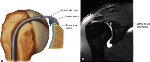
Type 2 BCL (see Fig. 8.74B; Fig. 8.76): The BLC is attached several millimeters medial to the sagittal plane of the glenoid. The superior pole of the glenoid continues its hyaline cartilage surface under the labrum. This configuration has a small sulcus at the superior pole of the glenoid that may be continuous with the more anterior variation of a sublabral foramen and communicate with the subscapularis bursa.60 This type of BLC
P.1201P.1202P.1203P.1204P.1205P.1206P.1207
attachment, with a triangular superior labrum and a free central edge, is associated with both the superior wedge labrum and the combined superior and anterior wedge labrum. -
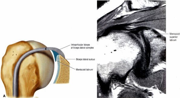
Type 3 BLC (see Fig. 8.74C; Fig. 8.77): The labrum is very meniscoid in shape and has a large sulcus that projects under the labrum and over the cartilaginous pole of the glenoid. It is seen in the meniscal or meniscoid (type E) labrum.
 |
|
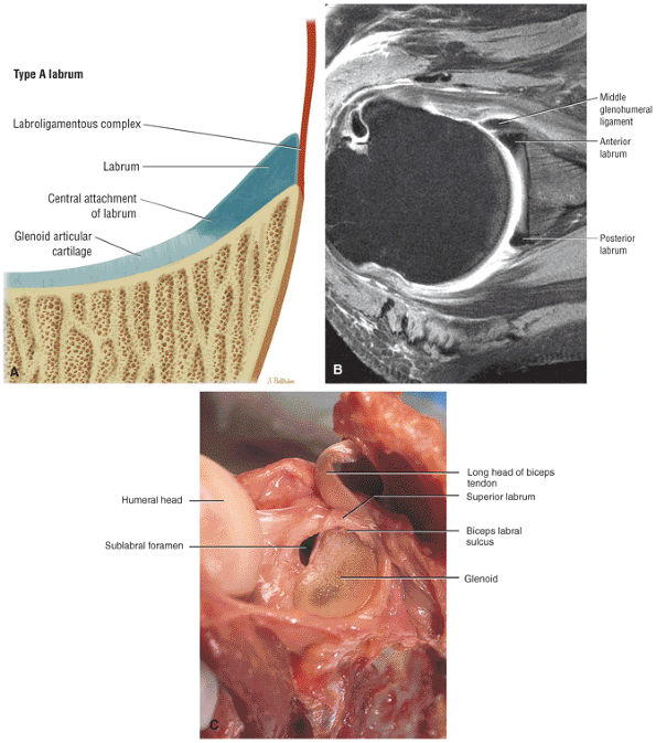
FIGURE 8.62 ● (A) The superior wedge labrum is characterized by a firm attachment of the anterior, posterior, and inferior labrum to the glenoid articular surfaces, with no free central edge. The superior labrum is, however, triangular in cross-section and its central free edge is separated and overlaps the articular cartilage at the biceps labral complex. An associated anterosuperior sublabral foramen is common in this labral type. (B) A superior wedge labrum is shown firmly attached to the anterior and posterior glenoid rim. The anterior band of the IGL blends with the labrum to form one structure near the equator of the anterior glenoid rim. A sublabral foramen may exist in the anterosuperior quadrant in a superior wedge labrum. (C) A superior wedge labrum in which the free central edge of the superior labrum forms the biceps labral sulcus of the biceps labral complex type 2. A sublabral foramen is an associated finding in the anterosuperior quadrant. Note the firm attachment of the anterior labrum (below the equator), posterior labrum, and inferior labrum.
|
 |
|
FIGURE 8.63 ● (A) The posterior wedge labrum is characterized by a posterior wedged-shaped labrum attached only at its periphery. A probe can be passed between the articular cartilage and the overlapping posterior labrum. When present, a well-defined posterior band of the IGL may overlap a relatively small posterior labrum, analogous to the anterior wedge labrum that occurs with a prominent anterior band. Anteriorly, superiorly, and inferiorly the labrum is firmly attached to the glenoid so that a probe cannot be passed between the glenoid articular surface and the labrum. The superior labrum is smaller than in the superior wedge labrum and is more firmly attached to the articular cartilage of the superior glenoid, as seen in the type 1 biceps labral complex (BLC 1). (B) A prominent or thick posterior band of the inferior glenohumeral ligament (IGL). This may be associated with a posterior wedge labrum. Normally the posterior band is not as well defined as the anterior band of the IGL. The posterior labrum may be relatively small underneath a prominent posterior band. Sagittal FS PD FSE image. (C) A posterior wedge labrum with free central edge of posterior labrum overlapping the posterior glenoid rim. From
Stoller DW. MRI, arthroscopy, and surgical anatomy of the joints. Philadelphia: Lippincott-Raven, 1999.
|
 |
|
FIGURE 8.64 ● (A) The anterior wedge labrum is firmly attached to the glenoid articular surface inferiorly, posteriorly, and superiorly. The anterior band (AB) of the IGHL, however, is thick and prominent and covers or overlaps the anterior labrum anterior to the anterior glenoid rim. The anterior wedge labrum may be further defined into two subtypes. The first subtype has a small anterior superior labrum, as already described, whereas the second subtype has an absent anterosuperior labrum underneath or deep to the prominent anterior band. Deep to the prominent anterior band of the IGHL, the anterior rim articular cartilage may taper and become thin peripherally. (B) The anterior band of the IGHL overlapping a small anterior labrum. Axial T1-weighted MR arthrogram.
|
 |
|
FIGURE 8.65 ● (A) Another labral variation is a combination of features of the superior wedge labrum and the anterior wedge labrum. A prominent or large anterior band of the IGL overlaps and may replace a small anterosuperior labrum. Superiorly the labrum has a free central margin and overlaps the glenoid articular cartilage, unlike the firmly attached superior labrum found in the anterior wedge labrum. There are three subtypes of this variant. In the first subtype there is no anterosuperior labrum. The second subtype has a small anterosuperior labrum firmly attached to the glenoid articular cartilage. In a third subtype the superior labrum and the anterior band of the IGL may blend together to form a free margin. This unattached free margin extends from the posterosuperior glenoid to the anteroinferior glenoid without an associated sublabral foramen anterosuperior. (B) Unattached free margin of superior labrum in a combination-type labrum.
|
 |
|
FIGURE 8.66 ● Meniscoid labrum with a circumferential free edge. This configuration is rare, and it is unusual to visualize an attached free margin involving the inferior labrum on MR studies. Fluid between the inferior labrum and glenoid articular cartilage on coronal MR images thus represents labral tearing. (A) Lateral color illustration with probing of the free labral margin and (B) corresponding gross specimen of meniscoid labrum.
|
 |
|
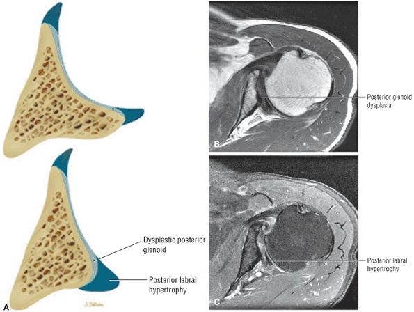
FIGURE 8.67 ● (A) Color axial section of normal posterior glenoid rim (top) compared to severe dysplastic posterior glenoid rim (bottom) with compensatory posterior labral hypertrophy. Axial T1 FSE (B) and axial FS PD FSE (C) images with severe posterior glenoid hypoplasia with thickened glenoid articular cartilage and posterior glenoid labral hypertrophy.
|
 |
|
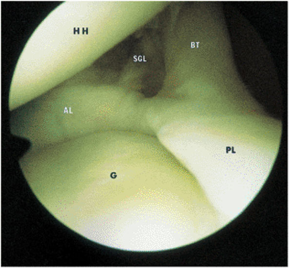
FIGURE 8.68 ● The biceps tendon (BT) contributes to the superior anterior labrum (AL) and the superior posterior labrum (PL) in the BLC. One component of the LHBT attaches to the supraglenoid tubercle. Extra-articular fibers attach to the lateral edge of the base of the coracoid process. The intra-articular portion of the LHBT is oriented at an approximate right angle to the surface of the glenoid (G). HH, humeral head; SGL, superior glenohumeral ligament.
|
 |
|
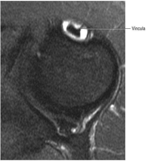
FIGURE 8.69 ● Vincula biceps extending anterior to the biceps tendon. Axial FS PD FSE image.
|
 |
|
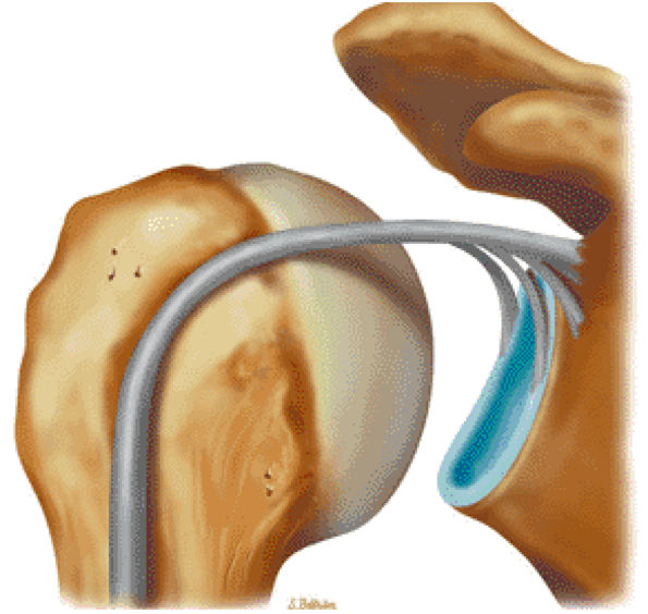
FIGURE 8.70 ● Origin of the long head of the biceps with idealized attachments to the posterior labrum, supraglenoid tubercle, anterior glenoid labrum, and base of the coracoid. (Based on
Detrisac DJ, Johnson LL. Biceps and subscapularis tendons. In: Detrisac DJ, Johnson LL eds. Arthroscopic shoulder anatomy: pathologic and surgical implications. Thorofare, NJ: Slack, 1986:21-34.
) |
pouch that attaches to the inferior two thirds of the entire circumference of the glenoid by means of the labrum (Figs. 8.80 and 8.81).37,62 The IGHL is lax in adduction and taut in abduction and external rotation (Fig. 8.82). As it tightens with increasing abduction, the anterior and posterior bands move superiorly with respect to the humeral head. At 90° of abduction, the IGHL is the primary restraint for anterior and posterior dislocations.63 The axillary pouch is located between the anterior and posterior bands and, like the anterior and posterior bands, is lax with the arm by the patient—s side in the adducted position. The axillary pouch extends inferior to the body of the glenohumeral joint as a redundancy of thickened capsular tissue best visualized on coronal oblique images.
 |
|
FIGURE 8.71 ● (A) Double biceps with two tendons inserting into the supraglenoid tubercle. (From
DePalma AF. Surgery of the shoulder, 3rd ed. Philadelphia: JB Lippincott, 1983.
) A bifid biceps tendon is shown in its extra-articular course on an axial T1-weighted arthrogram (B) and a corresponding gross dissection (C). |
 |
|
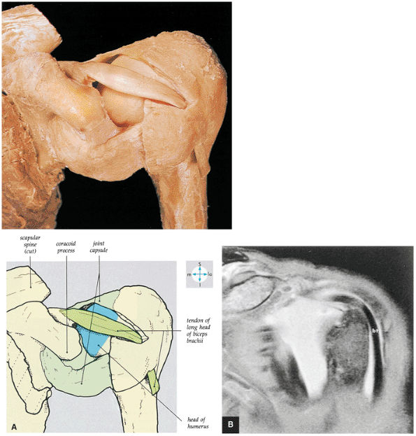
FIGURE 8.72 ● (A) Removal of part of the shoulder joint capsule reveals the intracapsular but extrasynovial tendon of the long head of the biceps brachii. (B) Corresponding anterior coronal (coronal oblique) FS MR arthrogram shows the course of the LHBT.
|
 |
|
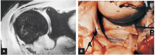
FIGURE 8.73 ● (A) The biceps origin can be located on a T2*-weighted coronal image. The glenoid origin of the long head of the biceps (b) is shown, as are the attachments to the anterior labrum (l) and superior glenoid (g). The biceps courses laterally and exits the joint between the supraspinatus (s) and subscapularis tendons. The axillary pouch (ap) of the IGHL is indicated. The tendon of the long head of the biceps enters the intertubercular groove under the transverse ligament. (B) Gross dissection demonstrates the anterior band (AB) and posterior band (PB) of the IGHL complex. This surgical view is from the perspective of viewing inferiorly into the axillary pouch. The anterior (A), posterior (P), and humeral head (HH) are indicated. Both the biceps tendon and posterior band contribute to the posterior labrum.
|
of the shoulder joint from 0° to 45° of abduction.59 Along with the subscapularis tendon and the superior part of the IGHL, the MGHL contributes to anterior stability at 45° of abduction.64 In the lower and middle ranges of abduction, the MGHL limits external rotation. The MGHL has also been shown to have a secondary role in anterior stability of the shoulder in 90° of abduction when the anterior band of the IGHL is cut.65 Inferior translation of the abducted and externally rotated shoulder is limited as a secondary restraint function of the MGHL. With internal rotation the MGHL demonstrates a more vertical orientation, and with external rotation it assumes a more horizontal orientation (elongation of the MGHL).
 |
|
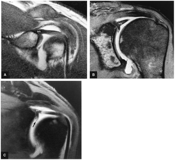
FIGURE 8.74 ● Biceps labral complex (blc) attachments. (A) In type 1, the BLC is firmly attached to the superior pole of the glenoid. m, middle glenohumeral ligament; ca, coracoacromial ligament. (B) In type 2, the biceps is attached to the superior labrum lateral to the superior glenoid. A fluid-filled sublabral sulcus (black arrow) is formed at the superior pole of the glenoid. Intermediate-signal-intensity cartilage (white arrow) of the glenoid extends medially over the superior glenoid surface. (C) Meniscoid labrum (large arrow) associated with a large sulcus (small arrow), which extends underneath the meniscoid superior labrum. FS T1-weighted coronal oblique MR arthrography images.
|
 |
|
FIGURE 8.75 ● (A) Type 1 BLC with superior labrum firmly attached to the superior pole of the glenoid. The type 1 BLC may be seen in the posterior wedge labrum and the anterior wedge labrum. (B) Coronal FS PD FSE image showing a type 1 BLC with a firm attachment of the superior labrum to the articular cartilage of the superior pole of the glenoid.
|
 |
|
FIGURE 8.76 ● (A) Type 2 BLC with a normal sulcus or separation of the free edge of the superior labrum from the superior pole of the glenoid. A type 2 BLC would be seen in the superior wedge labrum and combination superior and anterior wedge labrum. (B) Type 2 BLC with a fluid-filled sulcus separating the superior labrum from the adjacent articular cartilage of the glenoid. The superior labrum is triangular in cross-section. The sulcus may become more prominent with external rotation; however, its medial-to-lateral separation should not exceed 5 mm. Coronal MR arthrogram.
|
 |
|
FIGURE 8.77 ● (A) Type 3 BLC with meniscoid superior labrum and a free central margin. (B) Coronal PD FSE image illustrating a large meniscoid superior labrum in a type 3 BLC.
|
of the humeral head. Warner et al. showed that the SGHL was well developed in 50% of shoulders.69 When present and well formed (developed), the SGHL represents the primary capsuloligamentous restraint to inferior translation of the unloaded, abducted shoulder joint.59,69 Both the SGHL and the CHL have an important role in forming the biceps pulley of the rotator cuff interval.
 |
|
FIGURE 8.78 ● Type 2 BLC with normal superior sulcus on coronal FS PD (A) and axial PD (B) images with intra-articular contrast. (C) Corresponding axial color cross-section demonstrating the sulcus of a type 2 BLC. This sulcus should not be mistaken for detachment of the superior labrum.
|
 |
|
FIGURE 8.79 ● (A) An oblique anterior view of the scapula and lateral part of the clavicle. The bones have been separated to show the articular surfaces of the AC joint and the sites of attachment of the coracoclavicular ligament. (B) The glenoid attachments of the anterior capsular ligaments including the superior glenohumeral ligament (SGHL or SGL), the middle glenohumeral ligament (MGHL or MGL), the anterior band of inferior glenohumeral ligament (IGHL or IGL), and the axillary pouch of IGHL. (C) Glenohumeral capsular and ligament attachments in anterior, posterior, and medial humeral projections. (A–C: Based on
Detrisac DJ, Johnson LL. Biceps and subscapularis tendons. In: Detrisac DJ, Johnson LL eds. Arthroscopic shoulder anatomy: pathologic and surgical implications. Thorofare, NJ: Slack, 1986:21–34.
) |
 |
|
FIGURE 8.80 ● (A) The axillary pouch of the IGHL is seen on a T1-weighted sagittal MR arthrogram. Arrows and ap, axillary pouch of IGHL; b, biceps tendon; s, supraspinatus tendon; sub, subscapularis tendon. (B) The IGHL complex. An arthroscopic photograph shows the anterior band (AB) and axillary pouch (AP) components of the inferior glenohumeral ligament (IGL) complex. The inferior pole of the glenoid (IP) and the anatomic neck attachments of the IGL complex (AN) are shown as viewed from the axillary pouch. HH, humeral head.
|
 |
|
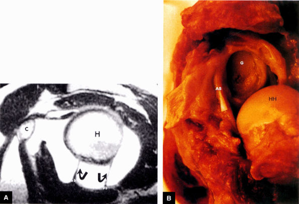
FIGURE 8.81 ● (A) The anterior band (ab) and posterior band (pb) of the IGHL (curved arrows) extend from the glenoid origin to the humeral attachment, as seen on an enhanced T1-weighted sagittal (oblique) image. C, coracoid; H, humeral head. (B) On a gross shoulder specimen, the superior course of the anterior band (AB) of the IGHL is identified (triangular marker). The glenoid (G) and humeral head (HH) are also identified.
|
 |
|
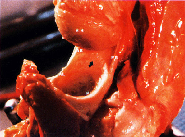
FIGURE 8.82 ● A gross shoulder specimen illustrates the structure of the inferior glenohumeral ligament (IGL) complex. With abduction of the humerus, the IGL structures are more prominent and taut in position. Coronal oblique MR images routinely show the lax axillary pouch of the IGL when the humerus is in the adducted position. Curved arrow, axillary pouch; AB, anterior band; AL, anterior labrum; HH, humeral head; PB, posterior band; PL, posterior labrum.
|
 |
|
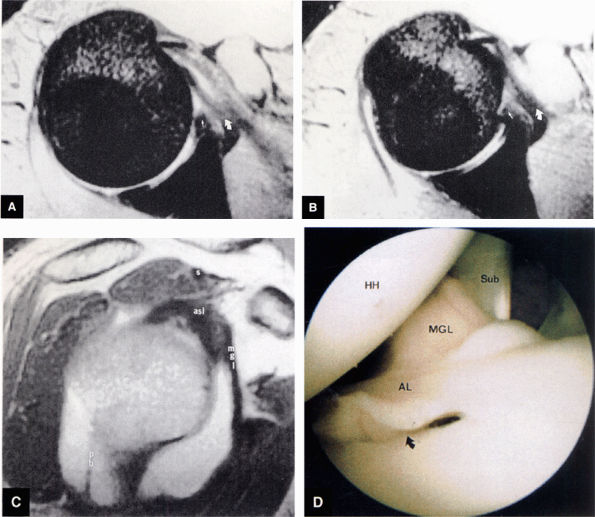
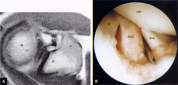
FIGURE 8.83 ● T2*-weighted axial images at (A) and below (B) the level of the subscapularis show the normal middle glenohumeral ligament (MGL; curved arrows), its medial origin from the glenoid and neck of the scapula, and its attachment to the lesser tuberosity. Small straight arrows, anterior labrum. (C) A T1-weighted sagittal oblique arthrogram shows the attachment of the MGL (mgl) to the anterior superior glenoid labrum (asl). The MGL arises from the labrum below the superior glenohumeral ligament and from the neck of the scapula. The humeral attachment of the MGL is located medial to the lesser tuberosity. Normal variants of the MGL include the ligament arising only from the labrum or having no attachment to it. pb, posterior band of IGL; s, supraspinatus tendon. (D) Arthroscopic view of the middle glenohumeral ligament (MGL) anterior to the anterior labrum (AL) and posterior to the subscapularis tendon (Sub). An anterior superior quadrant sublabral foramen (curved arrow) exists as a normal variant. HH, humeral head.
|
 |
|
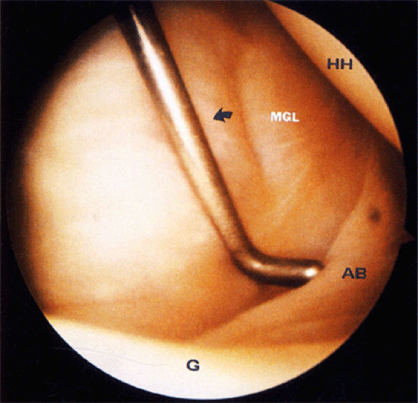
FIGURE 8.84 ● An arthroscopic photograph shows the anterior band (AB) of the IGHL. The subscapularis tendon (arrow) is located beneath the middle glenohumeral ligament (MGL) and is not directly seen. G, glenoid; HH, humeral head.
|
 |
|
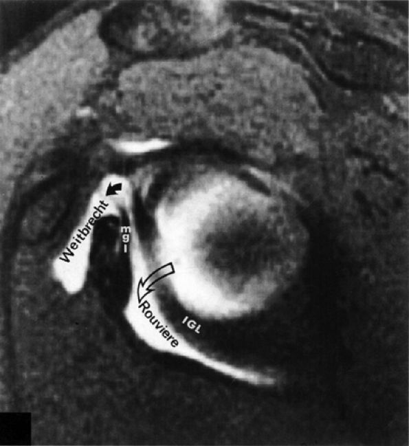
FIGURE 8.85 ● Normal foramen of Weitbrecht (solid curved arrow) is shown between the middle glenohumeral ligament (MGL) and the superior glenohumeral ligament. The foramen of Rouviere (open curved arrow) is located between the MGL and the inferior glenohumeral ligament (IGL).
|
 |
|
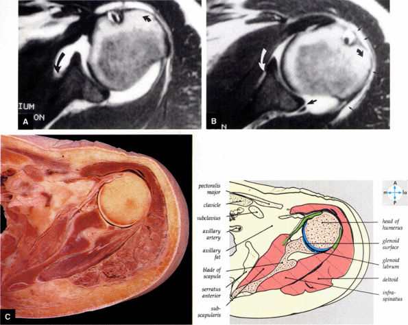
FIGURE 8.86 ● Normal variation in morphology of the subscapularis bursa is seen with (A) internal rotation and (B) external rotation on gadolinium-enhanced T1-weighted axial images. The subscapularis bursa has the appearance of a type 3 capsular insertion (long black curved arrow) in internal rotation (short black curved arrow) and a type 1 capsular insertion (long curved white arrow) in external rotation (short black curved arrow). Gadolinium contrast between the posterior band of the IGHL and the posterior labrum (large straight black arrow) and gadolinium contrast lateral to the humeral head in the subacromial bursa (small straight black arrows) are indicated. (C) A transverse section at the level of the humeral head shows the relations of the glenohumeral joint.
|
 |
|
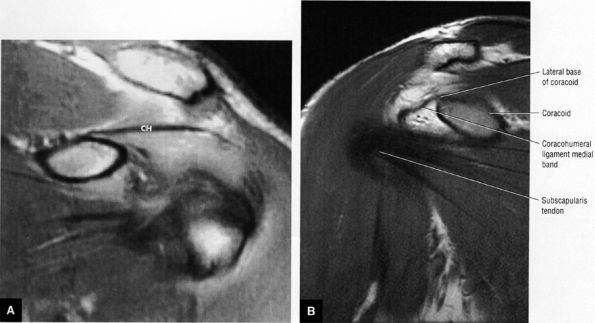
FIGURE 8.87 ● (A) The superior glenohumeral ligament (SGHL) is seen on an enhanced T1-weighted axial image above the level of the coracoid. The extra-articular coracohumeral ligament (CH) and intra-articular SGHL are closely related. The middle portion of the CH crosses the SGHL. The SGHL is oriented perpendicular to the middle glenohumeral ligament (MGL) as shown. BT, biceps tendon; G, glenoid; H, humeral head. (B) Arthroscopic photograph (posterior view) showing the lateral location of the biceps (B) relative to the superior glenohumeral ligament (SGHL). HH, humeral head; Sub, subscapularis tendon.
|
capsule, posterior dislocation does not occur even with division of the posterior capsule. The posterior capsule is torn in reverse HAGL lesions.73
 |
|
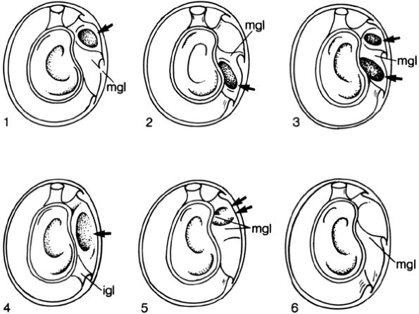
FIGURE 8.88 ● Six arrangements of synovial recesses (i.e., joint capsule variations, arrows) are described by DePalma. Type 1: One synovial recess exists above the middle glenohumeral ligament. Type 2: One synovial recess exists below the middle glenohumeral ligament. Type 3: Two synovial recesses exist, with a superior subscapular recess above the middle glenohumeral ligament and an inferior subscapular recess below the middle glenohumeral ligament. Type 4: No middle glenohumeral ligament is present, and one large synovial recess exists above the inferior glenohumeral ligament. Type 5: The middle glenohumeral ligament exists as two small synovial folds. Type 6: Complete absence of synovial recesses. (From
DePalma AF. Surgery of the shoulder. Philadelphia: JB Lippincott, 1983.
) |
 |
|
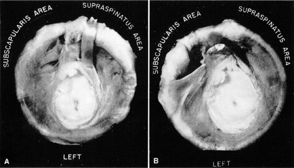
FIGURE 8.89 ● (A) Small synovial recesses above and below the middle glenohumeral ligament. (B) Large synovial recess above the middle ligament. This recess may be interpreted erroneously as a rent in the capsule. (From
DePalma AF. Surgery of the shoulder, 3rd ed. Philadelphia: JB Lippincott, 1983
, with permission.) |
 |
|
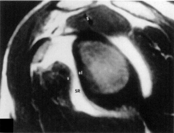
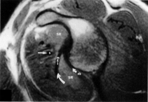
FIGURE 8.90 ● A single type 4 synovial recess. T1-weighted sagittal oblique arthrogram displays absence of the middle glenohumeral ligament, resulting in one large synovial recess above the inferior glenohumeral ligament. S, supraspinatus tendon; SR, synovial recess; s, subscapularis tendon.
|
 |
|
FIGURE 8.91 ● Sagittal MR image with two synovial recesses. Synovial recesses are present above and below the middle glenohumeral ligament. SR, synovial recess; S, subscapularis; mgl, middle glenohumeral ligament; ab, anterior band; straight arrow, subscapularis tendon; small curved arrow, superior course of mgl; large curved arrow, superior course of anterior band.
|
 |
|
FIGURE 8.92 ● Coronal PD-weighted images showing (A) the lateral band of the coracohumeral ligament inserting on the greater tuberosity and anterior border of the supraspinatus and (B) the medial band of the coracohumeral ligament inserting on the lesser tuberosity, the superior fibers of the subscapularis, and the transverse ligament.
|
 |
|
FIGURE 8.93 ● The coracohumeral ligament (CHL) inserts on either side of the bicipital groove rotator interval. The CHL and the superior glenohumeral ligament help stabilize the biceps tendon by forming a biceps pulley.
|
-
The infraspinatus muscle (Fig. 8.100) is bipennate and has a median raphe,74 which at surgery may be mistaken for the border between the infraspinatus and teres minor.
-
The subscapularis tendon lies on the anterior aspect of the anterior capsule of the glenohumeral joint, and its superior portion is intra-articular.48 The subscapularis bursa lies between the subscapularis tendon and the scapula. The subscapularis muscle may be the cause of recurrent instability as it becomes attenuated from repeated dislocations.44
-
The rotator cuff interval is located between the superior aspect of the subscapularis tendon and the inferior aspect of the supraspinatus tendon. This interval contains the coracohumeral ligament and the SGHL. A hidden lesion of the rotator interval has been attributed to pathology of the CHL–SGHL confluence, which forms the biceps sling or pulley. Surgical closure of the interval appears to eliminate excessive inferior translation.59
-
The triangular space through which the scapular circumflex vessels travel is formed by the teres major, the lower border of the teres minor, and the long head of the triceps.
-
Lateral to the triangular space, the quadrilateral space (through which the axillary nerve and posterior humeral circumflex artery travel) is formed by the lower border of the teres minor, the upper border of the teres major, the lateral border of the LHBT, and the medial border of the humerus.44
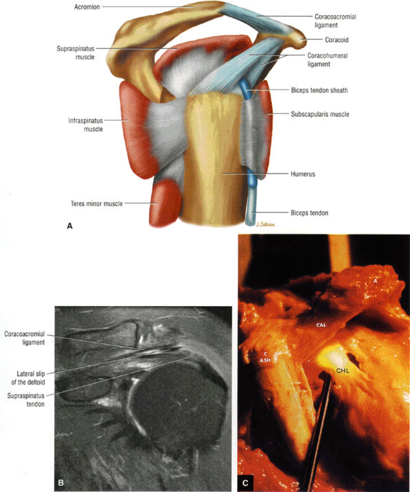
inferior surfaces of the acromion. The coracoacromial arch stabilizes the humeral head and prevents superior ascent (Fig. 8.102). The subacromial bursa is located between the acromion, the coracoacromial ligament, and the rotator cuff.44 The bursa runs from the AC joint medially, under the anterior third of the acromion and coracoacromial ligament, to a line that extends approximately 4 cm anterior and lateral to the anterolateral margins of the acromion. Anterior acromial spurs, caused by chronic irritation from the humerus in contact with this ligamentous structure, may form within the acromial portion of the coracoacromial ligament.46 Frequently, anterior acromial spurs are identified adjacent to the acromial attachment of the coracoacromial ligament. The normal low-signal-intensity acromial attachment of the coracoacromial ligament is frequently mistaken for an anterior acromial spur on coronal oblique MR images. The additive thickness of the coracoacromial ligament and the inferior acromial cortex produces this pseudospur (Fig. 8.103). In acromioplasty performed for chronic impingement, the coracoacromial ligament and the anterior inferior margin of the acromion are resected.
 |
|
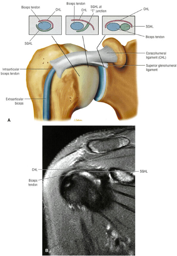
FIGURE 8.94 ● (A) The biceps pulley complex is sectioned in the sagittal plane at the level of the proximal, middle, and distal rotator cuff interval. The confluence of the CHL and SGHL occurs at the middle and distal aspects of the rotator interval. A T-shaped junction is formed between the SGHL and CHL at the mid-interval, superior to the humeral head. An anterior U-shaped sling is shown at the distal interval at the entrance to the bicipital groove. (B) An anterior coronal FS PD FSE image demonstrates the biceps tendon contained between the CHL and SGHL components of the biceps pulley.
|
 |
|
FIGURE 8.95 ● Sagittal MR arthrograms. (A) The anterior biceps sling is formed by the confluence of the CHL and SGHL anterior to the LHBT. (B, C) The T-shaped junction of the SGHL and CHL at the midportion of the rotator cuff interval.
|
 |
|
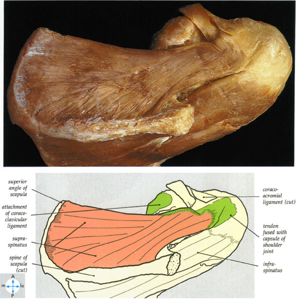
FIGURE 8.96 ● A superior view of the supraspinatus tendon after removal of the acromion of the scapula.
|
 |
|
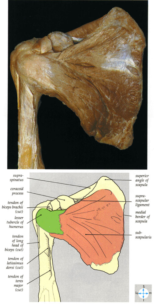
FIGURE 8.97 ● An anterior view of the subscapularis. The attachment of the serratus anterior to the medial border of the scapula has been excised.
|
 |
|
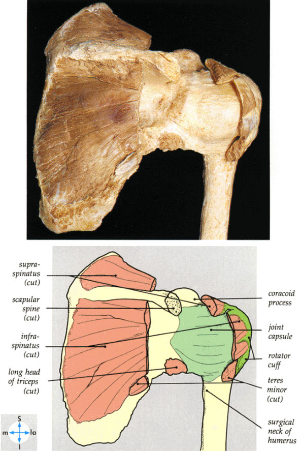
FIGURE 8.98 ● The posterior aspect of the shoulder joint. The acromion and parts of the rotator cuff muscles have been excised to reveal the joint capsule.
|
 |
|
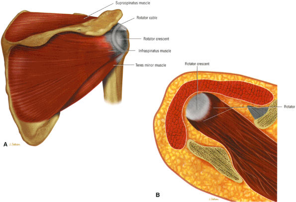
FIGURE 8.99 ● (A) The rotator cable and crescent shown from a posterior view. The cable represents thickened capsular tissue from the articular side of the cuff connecting the anterior and posterior tendon edges of the tendinous portion of the rotator cuff. An extension of the coracohumeral ligament contributes to the cable. The rotator crescent, especially the lateral portion of the supraspinatus peripheral to the cable, represents the concave portion of the cuff at risk for pathology. (B) A superior view of the rotator cuff ridge or cable.
|
 |
|
FIGURE 8.100 ● The bipennate infraspinatus muscle.
|
 |
|
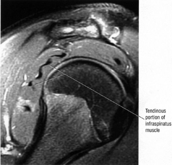
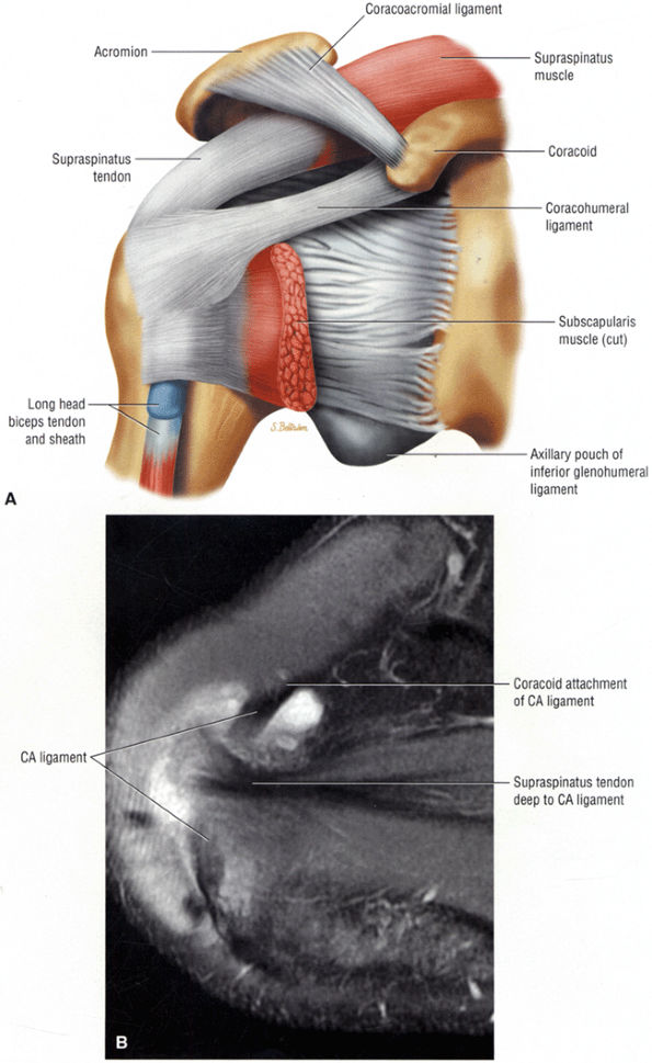
FIGURE 8.101 ● (A) The coracoacromial ligament extends from the inferior surface of the acromion to the lateral aspect of the coracoid. The humeroscapular motion interface represents a relationship between the rotator cuff, the humeral head, the biceps, the coracoacromial arch, and the deltoid and the coracoid muscles. Contact and load transfer occur between the rotator cuff and coracoacromial arch. (B) Coronal FS PD FSE image demonstrates the course of the coracoacromial ligament to the undersurface of the acromion. The lateral slip of the deltoid extends between the coracoacromial ligament and the rotator cuff. (C) Gross specimen highlighting the anatomy of the coracohumeral ligament (CHL) and coracoacromial ligament (CAL). The coracobrachialis (C), the short head of the biceps (SH), and the acromion (A) are indicated.
|
 |
|
FIGURE 8.102 ● (A) The anterior undersurface of the acromion and the coracoacromial ligament form the coracoacromial arch. The subacromial subdeltoid bursa facilitates the passage of the rotator cuff and proximal humerus under the coracoacromial arch. (B) A superior axial image shows the anterior-to-posterior extent of the coracoacromial (CA) ligament perpendicular to the supraspinatus tendon. The fluid in the subacromial-subdeltoid bursa represents fluid between two serosal surfaces in contact with each other. One serosal surface is contributed by the undersurface of the coracoacromial arch and deltoid, and the other serosal surface is on the bursal side of the cuff.
|
 |
|
FIGURE 8.103 ● Pseudospur. The normal broad attachment of the coracoacromial ligament to the inferior surface of the acromion is shown on (A) T1-weighted coronal oblique and (B) sagittal oblique images. The low-signal-intensity acromial cortex (black arrows) and adjacent coracoacromial ligament and lateral slip of the deltoid attachment (white arrows) give the false impression of a small subacromial spur in the coronal plane. This pseudospur should not be misinterpreted as impingement; otherwise, unnecessary acromioplasties may be performed on patients with a normal coracoacromial ligament attachment and no associated acromial spurs.
|
-
Impingement syndrome, a clinical diagnosis, is characterized by a range of MR findings from tendinosis to rotator cuff tears.
-
Intrinsic impingement is associated with shoulder instability.
-
Primary extrinsic impingement is associated with abrasion of the rotator cuff against the inferior surface of the acromion.
-
Subacromial keel spurs are located on the anteroinferior lateral portion of the acromion.
-
Acromial thickness is important in planning subacromial decompression procedures.
-
The AC joint may hypertrophy, but it is not responsible for true impingement.
-
The imaging reference to hypertrophy of the coracoacromial ligament correlates with fraying or fragmentation of the ligament in association with impingement.
-
A symptomatic os acromiale is associated with marrow edema on either side of the synchondrosis.
-
Degenerative tendinopathy or intrinsic tendon degeneration associated with eccentric tensile overload may be the primary pathology in impingement.
-
Rotator cuff tendinosis is most conspicuous on FS PD FSE images. It does not demonstrate hyperintensity on T2 FSE images. Partial- and full-thickness tears are hyperintense on both FS PD FSE and T2 FSE sequences unless associated with chronic scarring or granulation tissue.
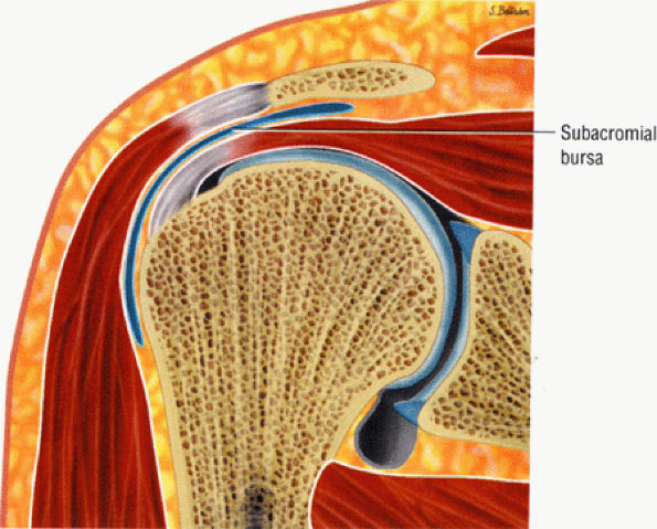 |
|
FIGURE 8.104 ● The subacromial bursa extends over the insertion of the supraspinatus superiorly and over the infraspinatus and teres minor posteriorly. The superior surface of the bursa is in contact with the undersurface of the acromion, the coracoacromial ligament, and the origin of the mid-portion of the deltoid muscle. The superior surface of the bursa extends medially adjacent to the deep surface of the acromioclavicular joint.
|
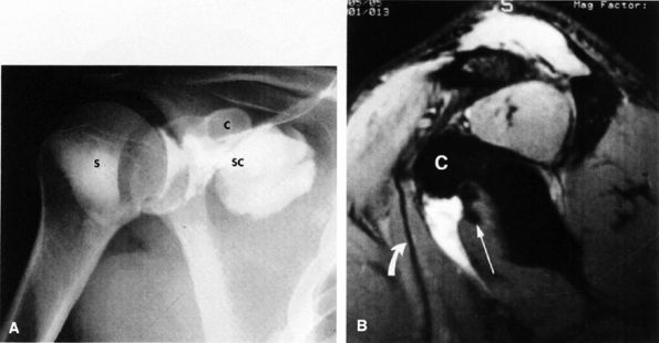 |
|
FIGURE 8.105 ● (A) After separate contrast injections into the subcoracoid (SC) and subscapularis (S) bursae, the subcoracoid and subacromial bursae are seen to communicate, whereas no communication occurs between the subacromial and subscapularis bursae. C, coracoid. (B) T2*-weighted sagittal oblique gadopentetate-saline subcoracoid bursagram demonstrates filling of the subcoracoid bursa anterior to the subscapularis tendon (straight arrow) and posterior to the conjoined tendon of the coracobrachialis and short head of the biceps (curved arrow). C, coracoid.
|
-
Hypovascularity in the supraspinatus tendon
-
Mechanical wear
-
Acute trauma
-
Repetitive microtrauma from overuse (this is especially common in throwing athletes or those whose work activities emphasize overhand motions)
-
Anterior acromial spurs
-
Acromion shape (a curved or overhanging edge)
-
The slope of the acromion (a flat or decreased angle)
-
The morphology of the AC joint (hypertrophic bone, callus formation)
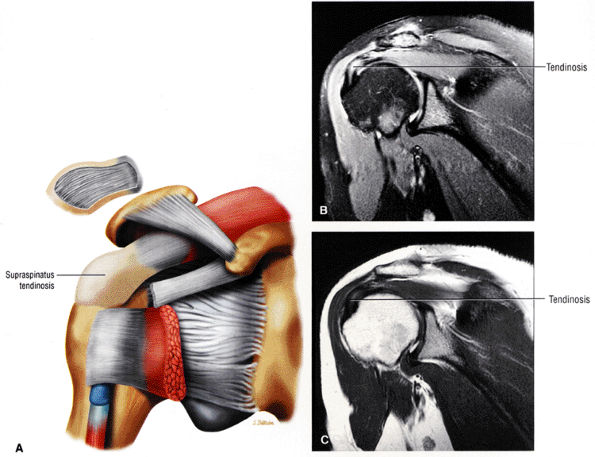 |
|
FIGURE 8.106 ● (A) Rotator cuff tendinosis is seen as collagen degeneration without the influx of inflammatory cells. The thickened distal cuff tendon is viewed in an anterior coronal perspective. Moderate to severe rotator cuff tendinosis demonstrates hyperintensity on a coronal FS PD FSE image (B) and intermediate signal intensity on a coronal T2 FSE image (C).
|
-
Prominence of the greater tuberosity (fracture, malunion, nonunion)
-
Loss of humeral head depressors,91 as seen in rotator cuff tears and biceps tendon rupture
-
Loss of the glenohumeral joint fulcrum function from articular surface destruction or ligamentous laxity
-
Impaired scapular rotation from trapezius paralysis or AC joint disruption
-
Lesions of the acromion, including an unfused anterior acromial epiphysis (apophysis)
-
Fracture malunion or nonunion
-
Subacromial bursal thickening (chronic bursitis or cuff thickening in calcific tendinitis)
os acromiale; inflammatory bursitis, malunion of the greater tuberosity, distal clavicle or acromion; and partial- or full-thickness tears of the rotator cuff. Dynamic causes of subacromial pathology include scapular dysfunction, primary tendon overload, glenohumeral instability, repetitive microtrauma, and an imbalance of shoulder musculature.
-
Posterior peel-back
-
Microinstabilities of the glenohumeral joint
-
Scapular dyskinesia
-
Greater tuberosity malunion
-
Loss of humeral head depressor function
-
Variations in anterior acromial shape
-
Slope of the acromion (lateral or anterior downsloping)
-
A low-lying acromial position
-
AC joint osteophytes
-
Anterior inferior acromial spurs
-
Coracoacromial ligament thickness
-
Os acromiale
-
The type 1 acromion (Fig. 8.107) has a flat or straight undersurface.
-
The type 2 acromion (Fig. 8.108) has a smooth, curved inferior surface that approximately parallels the superior humeral head in the sagittal oblique plane.
-
The type 3 acromion (Fig. 8.109) has an anterior hook or beak. The acromiohumeral distance is narrowed relative to the remainder of the acromion at the site of the hook. It is the type 3 acromion that is thought to be associated with a greater predisposition to rotator cuff tears (i.e., tears involving the critical zone immediately proximal to the greater tuberosity insertion of the supraspinatus tendon). In the clinical series of Morrison and Bigliani,94 80% of patients with rotator cuff tears had type 3 acromions.
-
The type 4 acromion, described by Vanarthos and Mono95 (Fig. 8.110), has a convex inferior contour. Although there may be partial narrowing of the subacromial space near the midposterior aspect of the distal acromion, there is no correlation between a type 4 acromion and impingement.
2 and 3 acromions may be acquired rather than developmental.98 Most acromial hooks lie within the coracoacromial ligament and may be traction spurs (analogous to the traction spur or enthesophyte seen in the plantar ligament at its attachment to the calcaneus). The traction loads producing such hooks may result from loading of the arch by the cuff. In the presence of cuff degeneration, dependence on the coracoacromial arch for superior stability increases, and so may the traction loads. The hypothesis that the hook is a traction phenomenon was first put forward by Neer.83,99 Putz and Reschelt99 reported that three quarters of operative specimens of the coracoacromial ligament showed chondroid metaplasia near the acromial insertion. This metaplastic area becomes the acromial hook by enchondral bone formation.100 Because the hook lies within the coracoacromial ligament and points toward the coracoid, it may not directly affect or jeopardize the passage of the cuff beneath the coracoacromial arch, as previously thought.
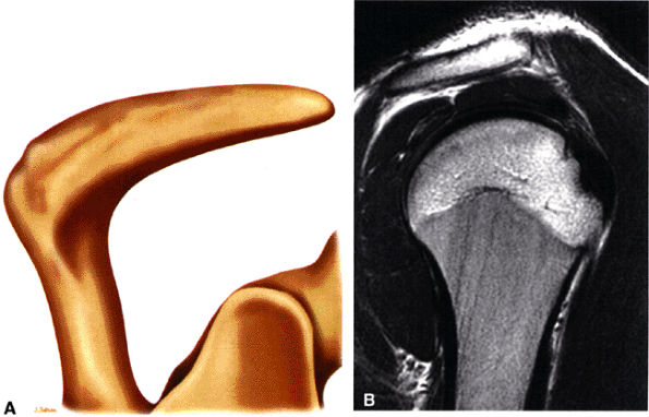 |
|
FIGURE 8.107 ● (A) Type 1 acromion with flat acromial undersurface. (B) Type 1 acromion with straight inferior margin as seen on a sagittal T2 FSE image.
|
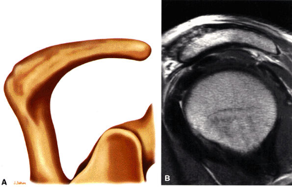 |
|
FIGURE 8.108 ● (A) Type 2 acromion with a curved convex inferior surface that parallels the contour of the humeral head. (B) Type 2 curved acromion on a corresponding sagittal PD FSE image.
|
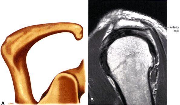 |
|
FIGURE 8.109 ● (A) Type 3 acromion with an inferiorly directed beak or hook, which contributes to narrowing of the supraspinatus outlet for the supraspinatus tendon. (B) Sagittal PD FSE image of the type 3 or anterior hooked acromion. The type 3 acromion is assessed at least one to two images lateral to the AC joint.
|
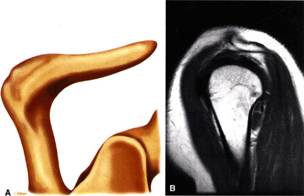 |
|
FIGURE 8.110 ● (A) Color illustration and (B) sagittal PD FSE image of a type 4 acromion with upward or superior convexity of its inferior border. There is no association with cuff impingement.
|
-
Type A acromion: thin, less than 8 mm
-
Type B acromion: 8 to 12 mm
-
Type C acromion: thick, more than 12 mm
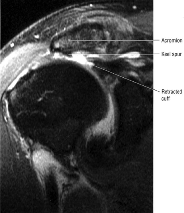 |
|
FIGURE 8.111 ● Coronal FS PD FSE image showing an acromial “keel” spur associated with a full-thickness rotator cuff tear with retraction.
|
-
Cross-est adduction (increasing symptoms)
-
Adduction, internal rotation, and extension (to isolate posterior AC facet pain)
-
Direct superior tenderness reproducing the pain
-
Tenderness on anteroposterior translation
-
Localized pain in the AC joint with impingement testing
meta-acromion failure (failure of fusion of the mesoacromion to the meta-acromion) is more common. The synchondrosis-like articulation may contain fibrous tissue, periosteum, or synovium. The os acromiale may be relatively mobile with shoulder abduction causing impingement.103 Degenerative changes across the os acromiale, including edema, also contribute to impingement. An unstable degenerative os acromiale is often associated with AC joint degeneration. The coracoacromial ligament inserts onto the os acromiale, and thus the os acromiale is susceptible to instability. Failure to recognize an os acromiale is associated with a failed acromioplasty.
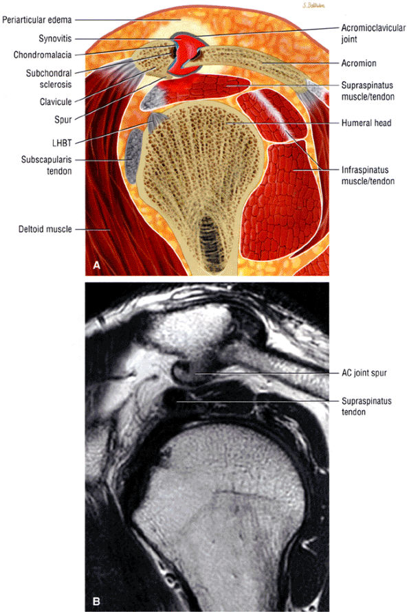 |
|
FIGURE 8.112 ● (A) Although AC arthrosis may be concurrent with impingement, it is the more lateral acromial spurs that are directly associated with symptomatic bursal-side cuff damage. (B) AC joint degenerative disease with hypertrophic inferior acromial side spur.
|
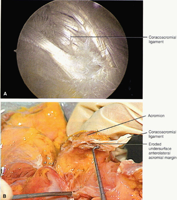 |
|
FIGURE 8.113 ● (A) Arthroscopic view from the subacromial space shows the fascicles of the coracoacromial ligament as they attach to the inferior aspect of the acromion. The coracoacromial ligament attaches to the anterior, lateral, and inferior surfaces of the acromion and originates as a triangular band of two fascicles from the lateral aspect of the coracoid. (B) The corresponding coracoacromial ligament has been cut, with the acromial attachment intact. (A, B: From
Stoller DW. MRI, arthroscopy, and surgical anatomy of the joints. Philadelphia: Lippincott-Raven, 1999
, with permission.) |
 |
|
FIGURE 8.114 ● Superior view of os acromiale subtypes from distal to proximal. These unfused ossification centers include pre-, meso-, meta-, and basiacromion based on the location of the articulation. The mesoacromion-meta-acromion type is most common.
|
-
Stage 1: Tendon edema and hemorrhage
-
Stage 2: Fibrosis and tendinitis
-
Stage 3: Partial or complete rupture or tear of the rotator cuff, often in association with anterior acromial spurring or greater tuberosity excrescence. When present, radiographic changes include greater tuberosity sclerosis and hypertrophic bone formation. Bursal thickening, fibrosis, and partial tears of the superficial rotator cuff may be present.
-
Type 1: Rotator cuff degeneration or tendinosis without visible tears of either surface
-
Type 2: Rotator cuff degeneration or tendinosis with partial-thickness tears of either articular or bursal surfaces
-
Type 3: Complete-thickness rotator cuff tears of varying size, complexity, and functional compromise
Rotator cuff degeneration has also been observed in the absence of anteroinferior acromial spurs.100 Ozaki et al.90 found that bursal side and full-thickness rotator cuff tears correlated with degenerative changes of the coracoacromial ligament and anterior third of the inferior acromion. Articular surface partial tears, however, were associated with normal acromial morphology and histology. Most tears of the rotator cuff were thus attributed to degenerative lesions that were associated with increasing age, and the acromial changes present were secondary. Athletes may demonstrate both degenerative rotator cuff tendinitis and primary mechanical impingement.105
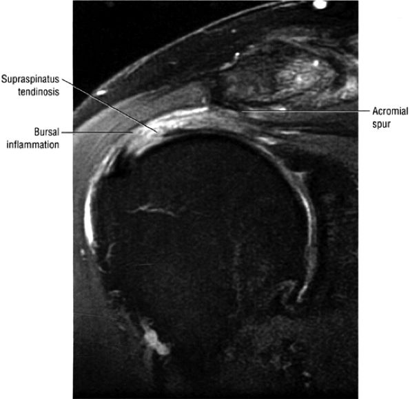 |
|
FIGURE 8.115 ● Coronal FS PD FSE image showing severe tendinosis with greater bursal-side involvement and an anterior inferior acromial spur.
|
bursal inflammation are usually associated with tendinitis or cuff tears, small amounts of subacromial bursal fluid may be seen without abnormal cuff morphology or signal intensity alterations. Low signal intensity within a thickened subacromial bursa on T1- and T2-weighted images indicates a proliferative process in chronic bursitis, also associated with rotator cuff disease.113 Subacromial bursal thickening occurs in Neer's stage 2 impingement, although the subacromial bursa may not show any surgical signs of scarring in chronic impingement.86,114 The presence or absence of subacromial fat, however, is a variable finding in asymptomatic volunteers and in the various stages of impingement. FS PD-weighted FSE images are more sensitive than conventional T2 or non-FS PD-weighted FSE sequences in identifying small amounts of subacromial bursal fluid on coronal oblique or axial images. The subacromial bursa may be distended with fluid in both partial and complete rotator cuff tears. It is unusual to see a fluid-filled bursa in the presence of a normal cuff. FS PD FSE images have a high sensitivity for small amounts of fluid, making assessment of loss of peribursal fat no longer relevant.
-
Although the subacromial peribursal fat plane is usually preserved on T1- or PD-weighted images in the early stages of impingement, it may be effaced by bursal surface inflammation in the absence of a rotator cuff tear.84
-
An area of increased signal intensity on T2-weighted (long TR/long TE) sequences may be caused by the injection of long-acting steroids and local anesthetics used in the diagnosis and treatment of impingement. Prior use of this technique should be taken into consideration to decrease false-positive diagnoses.82
-
In addition to articular and bursal tendon degeneration, intrasubstance degeneration may also be associated with intrasubstance tears without bursal or articular surface extension. Although intrasubstance cuff pathology can be identified on MR images, these changes are usually not confirmed on arthroscopic surface evaluations. Conventional and Gd-DTPA–enhanced MR images are also negative for intrasubstance degeneration and tear.
are seen as an age-related phenomenon in older patients and in normal asymptomatic volunteers. More severe changes of degeneration may be characterized by intermediate to increased signal intensity on short-TE or T1- and PD-weighted images, which persist without further increase in signal intensity on T2-weighted images. These tendons may appear gray on long-TE sequences. Increased signal intensity on short- and long-TE images (conventional T2 and FSE T2), with a further increase in signal intensity between T1 or PD and T2-weighted images, is associated with a partial- or full-thickness tear. Differentiating severe tendinitis and partial tears may require careful attention to the continuity of the bursal and articular surfaces of the cuff as well as the increased signal intensity observed on both short- and long-TE images. Secondary findings of musculotendinous retraction and atrophy of the supraspinatus muscle are seen with complete cuff tears. Low signal intensity may be identified on T2-weighted images in areas of severe degeneration or tear obliterated by scar tissue or tendon remnants.122 Fraying of the cuff may be appreciated as a surface contour irregularity involving either the articular or bursal surface (Fig. 8.117).
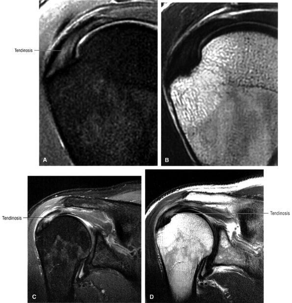 |
|
FIGURE 8.116 ● (A) Infraspinatus tendinosis appears hyperintense on this FS PD FSE coronal image. (B) Corresponding T2 FSE coronal image shows intact bursal and articular cuff surfaces. Note that cuff degeneration is visualized as intermediate signal intensity, thus increasing the specificity of this imaging sequence. (C) A separate area of infraspinatus tendinosis that may be mistaken for a partial articular-side tear is displayed on this FS PD FSE image. (D) A coronal T2 FSE image demonstrating tendinosis with no hyperintensity of cuff fibers.
|
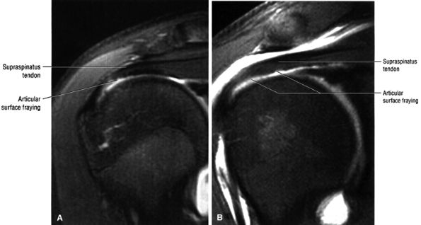 |
|
FIGURE 8.117 ● (A) Articular surface fraying of the supraspinatus in a gymnast. (B) Coronal FS PD FSE MR arthrogram in a separate case of articular surface fraying.
|
-
Type 1 impingement is characterized by the presence of subacromial bursitis, and signal intensity in the supraspinatus may remain normal. Isolated subacromial bursitis is an infrequent finding on MR images; however, it is usually associated with tendinitis. This is substantiated by postmortem and histologic studies from the surgical literature.123,124,125,126,127
-
In Seeger's type 2 impingement, the supraspinatus tendon demonstrates increased signal intensity on T1-weighted images. Increased signal intensity on T2-weighted images is considered a type 2b change and may represent a partial tear.
-
Type 3 impingement is characterized by a complete tear of the rotator cuff, with or without supraspinatus retraction. Complete tears exist only in type 3 impingement, and in this classification system high signal intensity of the supraspinatus tendon on conventional T2-weighted images is considered pathognomonic for a tear.
-
Type 1 impingement is characterized by signs of tendon wear or degeneration on the articular or bursal surface, with associated fraying or irregularity of either articular or bursal structures. Type 1 impingement is subdivided into type 1a (articular) and type 1b (bursal). Type 1 impingement also includes any signs of wear or degeneration of any of the structures in the bursa (e.g., coracoacromial ligament erosion or fraying). In addition to articular (type 1a) and bursal (type 1b) tendon degeneration, intrasubstance degeneration, which we refer to as type 1c, may be associated with intrasubstance partial tears (Fig. 8.118). Such intrasubstance degeneration is not detected and cannot be confirmed on arthroscopic surface evaluations. Conventional and gadolinium-enhanced MR images are negative in type 1 impingement.
-
In type 2 impingement, in addition to tendon wear or degeneration, there are partial-thickness tears, of the articular surface in type 2a (Fig. 8.119) or the bursal surface in type 2b (Fig. 8.120). Type 2 impingement lesions are also characterized on MR images as partial articular
P.1249P.1250P.1251
(type 2a) or bursal (type 2b) tears. In the presence of a surface tear, it may be difficult and redundant to classify associated intrasubstance changes, whether secondary to degeneration or intrasubstance tearing. Cadaveric histopathologic studies have shown that partial tears may originate from regions of tendon degeneration without associated inflammation, as discussed earlier.115 Coronal oblique MR images show increased signal intensity in the distal supraspinatus tendon on T1-, intermediate-, T2-, T2*-, and T2-weighted FSE images. Increased-signal-intensity fluid within the bursal or articular surface of the cuff is characteristic of this lesion. Small amounts of fluid may be seen in the subacromial bursa, especially in bursal surface type 2b lesions, in the absence of a full-thickness or complete tear. In addition to a partial-thickness tear, in type 2 impingement associated tendon thinning and fraying may be present. Well-defined, linear high signal intensity on T2-weighted images, or an area of increased signal intensity on long-TR/TE images, that does not extend to either the articular or bursal surfaces may represent intrasubstance partial tears. Morphologic tendon changes, such as tendon irregularities or thinning, help support the diagnosis. -
Type 3 impingement is characterized by a full-thickness tear of the rotator cuff. Without retraction of the cuff, the tear is classified as type 3a; with retraction of the cuff, it is classified as type 3b. MR imaging may depict a complete tear of the rotator cuff (type 3a impingement) or a tear with proximal tendon retraction (type 3b impingement). Without demonstration of a defined defect, retraction of the muscle belly, or extension of fluid across the supraspinatus tendon into the subacromial-subdeltoid bursa, a complete tear cannot be unequivocally diagnosed. Increased signal intensity within the tendon on T2-weighted images in the presence of normal tendon morphology is not diagnostic of a rotator cuff tear. Therefore, the presence of small amounts of fluid within the subacromial-subdeltoid bursa should not be used as a primary sign of rotator cuff tear, unless associated with a direct communication of fluid from the glenohumeral joint into the subacromial-subdeltoid bursa.
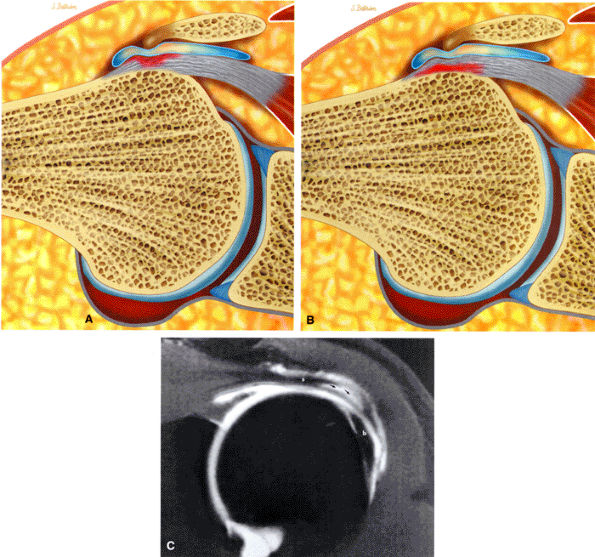 |
|
FIGURE 8.118 ● (A) Subacromial impingement with subacromial bursal inflammatory changes and development of a bursal-side partial tear of the rotator cuff. (B) Articular-side partial tear in subacromial impingement. Bursal inflammatory changes may be present with both bursal and articular side pathology. (C) Surgically confirmed intrasubstance tear (arrows) with intact bursal and articular cuff surfaces on an FS T1-weighted coronal oblique MR arthrogram. The biceps tendon (b) and supraspinatus tendon (s) are identified.
|
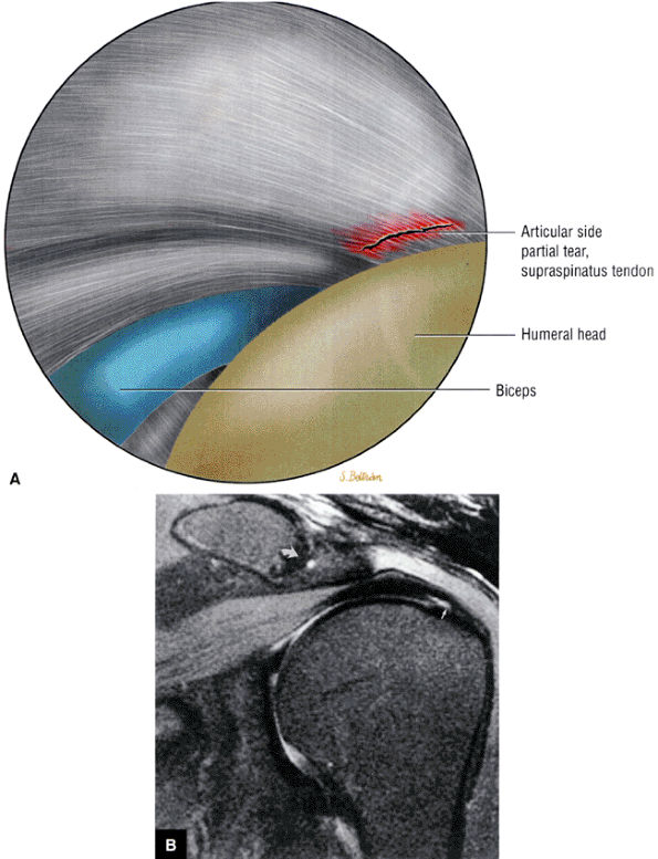 |
|
FIGURE 8.119 ● (A) Articular-side partial-thickness supraspinatus tendon tear. Arthroscopic view from the glenohumeral joint using the posterior portal. (Based on
Johnson TS, Warren RF. Arthroscopic subacromial decompression and rotator cuff debridement. In: Craig EV, editor. The shoulder, 2nd ed. Philadelphia: Lippincott Williams & Wilkins, 2004:3–20.
) (B) Partial articular surface tear (straight arrow) is hyperintense on FS PD-weighted FSE coronal oblique image. A corsinosis is indicated (curved arrow). |
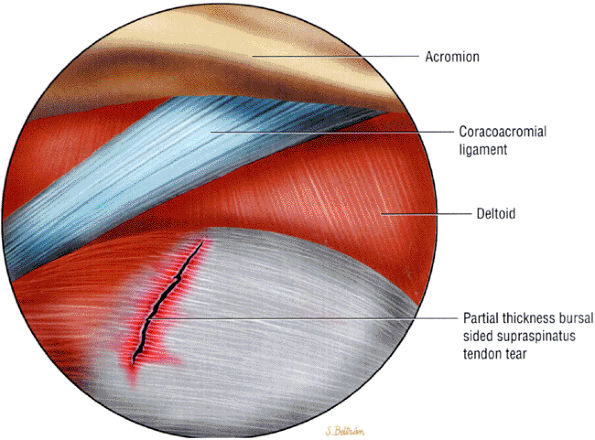 |
|
FIGURE 8.120 ● Partial-thickness bursal-side rotator cuff tear as viewed from a posterior arthroscopic portal. (Based on
Johnson TS, Warren RF. Arthroscopic subacromial decompression and rotator cuff debridement. In: Craig EV, ed. The shoulder, 2nd ed. Philadelphia: Lippincott Williams & Wilkins, 2004:3–20.
) |
anteroposterior (outlet view) radiographs. They arise in or adjacent to the acromial attachment to the coracoacromial ligament and are thought to represent traction osteophytes.75 Acromial spurs containing marrow fat demonstrate high signal intensity on T1-weighted images. They may, however, blend with the adjacent acromial cortex on FS PD-weighted images, obscuring their identification. Anterior acromial spurs are intermediate in signal intensity and may be overlooked on conventional T2 and T2-weighted FSE sequences. The anterior and inferior location of the spur is best shown on sagittal oblique images. Larger spurs are evident on coronal oblique images. Spurs are composed of primary cortical bone and are low in signal intensity on all pulse sequences. It is important not to misinterpret the normal inferior acromial attachment of the coracoacromial ligament or lateral deltoid attachment as an acromial spur. An area of suspected cortical thickening on the inferior acromial surface, as identified on coronal oblique images, should be verified on corresponding sagittal oblique images. Anterior inferior acromial spurs, although less common than AC joint osteophytes, have a higher predictive value for rotator cuff pathology.
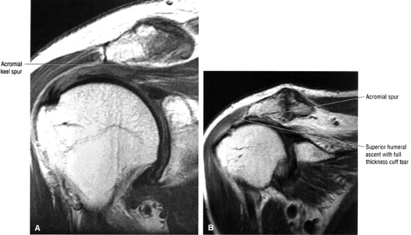 |
|
FIGURE 8.121 ● (A) Coronal PD FSE image illustrates a true acromial “keel” spur associated with cuff impingement. Keel spurs are considered aggressive with respect to their potential to cause damage to the bursal side of the cuff if not removed. (B) Complete chronic rotator cuff tear associated with anterior inferior acromial “keel” spur. The associated hypertrophic AC joint is not as important in the pathogenesis or progression of impingement to cuff tear.
|
anterior inferior cortex of the acromion is more inferiorly located relative to its posterior cortex as assessed in the sagittal oblique plane. The normal acromion is usually shown as nearly horizontal in its lateral aspect on sagittal oblique images. As discussed in the case of the flat or decreased acromial angle, an anterior downsloping acromion is thought to be associated with an increased risk for anterior acromial impingement.132
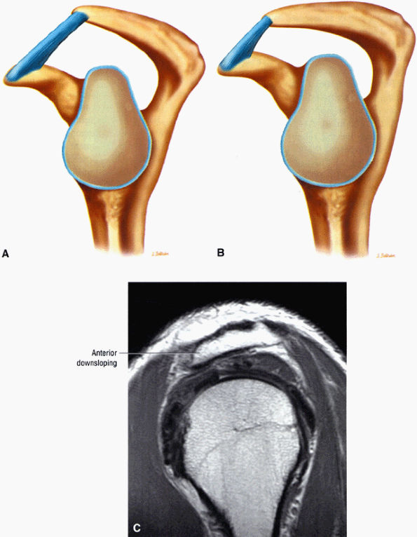 |
|
FIGURE 8.122 ● (A) Normal upward-oriented acromial slope. (B) Anterior downsloping acromion with narrowed supraspinatus outlet. (C) Anterior downsloping acromion on sagittal PD FSE image.
|
humeral head can vary from a few millimeters to up to 2 or 3 cm in diameter. There is a normal absence of articular cartilage in this region. The bare area is associated with either indentations or deep holes representing vascular access channels to the subchondral bone. In comparison, the Hill-Sachs lesion is located more medially and is surrounded by otherwise normal articular cartilage.73
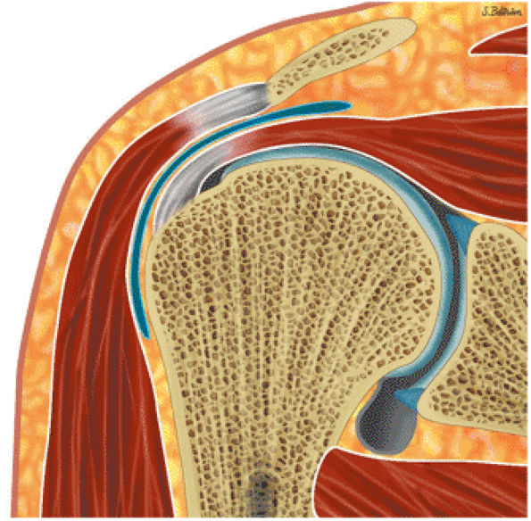 |
|
FIGURE 8.123 ● Lateral downsloping acromion as viewed on coronal section.
|
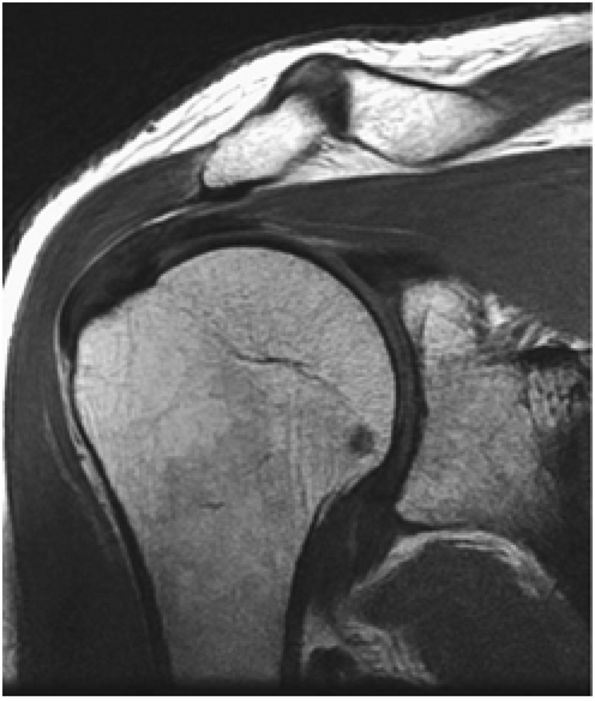 |
|
FIGURE 8.124 ● Lateral downsloping acromion assessed on coronal FSE image.
|
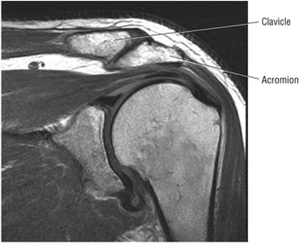 |
|
FIGURE 8.125 ● Inferior projection of the acromion relative to the distal clavicle. Mild arthrosis is also shown on this coronal T2 FSE image.
|
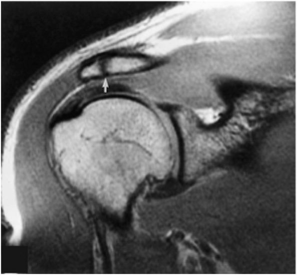 |
|
FIGURE 8.126 ● Asymptomatic os acromiale (arrow) without associated marrow changes on T1-weighted coronal (oblique) image.
|
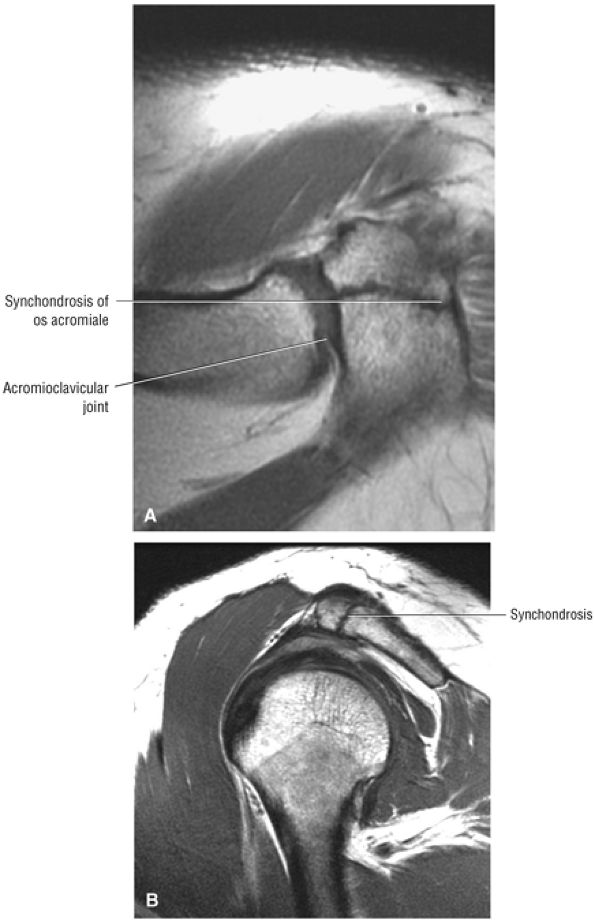 |
|
FIGURE 8.127 ● Preacromion without degenerative changes. (A) The synchondrosis and the AC joint are shown together on this axial PD FSE image. (B) On this sagittal PD FSE image the synchondrosis could be mistaken for an AC joint.
|
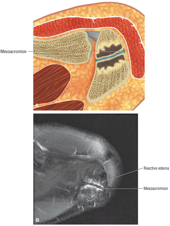 |
|
FIGURE 8.128 ● A mesoacromion with degenerative change and osseous edema across the synchondrosis is shown on an axial color illustration (A) and an axial FS PD FSE image (B).
|
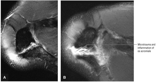 |
|
FIGURE 8.129 ● (A) A painful mesoacromion synchondrosis in a basketball player. (B) Subsequent severe inflammation of the os acromiale after 6 weeks of intensive weight lifting. Axial FS PD FSE images.
|
 |
|
FIGURE 8.130 ● AC joint arthrosis with subchondral cystic changes (A) and edema (B) of the distal clavicle and adjacent acromion.
|
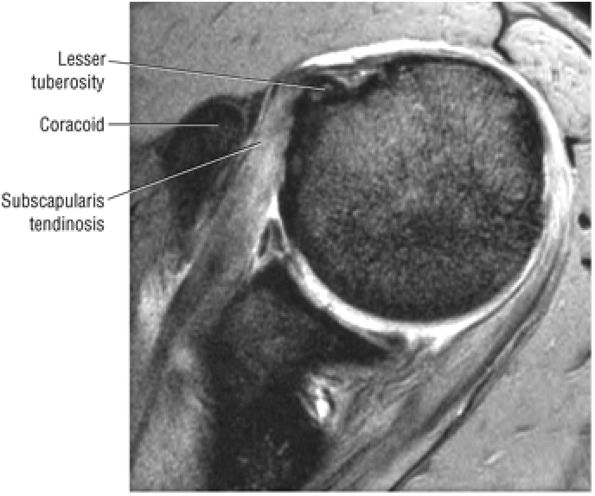 |
|
FIGURE 8.131 ● Subcoracoid impingement with narrowing of the space between the coracoid and the insertion of the subscapularis tendon on the lesser tuberosity. Hyperintense subscapularis tendinosis is shown on this axial T2* GRE image.
|
and sleep levels are often unacceptable to the patient. Therefore, if pain reduction through conservative measures is not achieved, an arthroscopic approach is warranted.
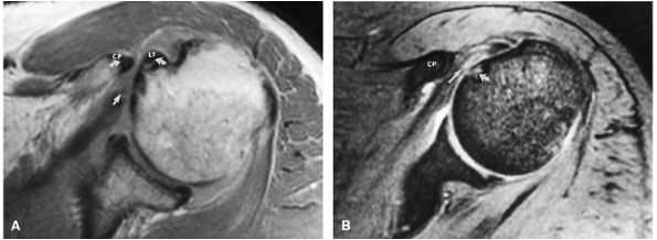 |
|
FIGURE 8.132 ● Coracoid impingement with narrowing (curved arrows) between the coracoid process (CP) and humeral head. Associated subscapularis tendon degeneration (straight arrow) and subchondral cystic change of the anteromedial humeral head (curved arrow) are shown on (A) T1 and (B) T2*-weighted axial images. LT, lesser tuberosity
|
with impingement, it is necessary to perform an arthroscopic Mumford procedure (i.e., resection of the distal 2 cm of the clavicle) at the same time as the ASD. If a degenerative prominence of the AC joint is producing extrinsic compression of the muscle belly of the supraspinatus, it can also be removed by resecting the distal clavicle.
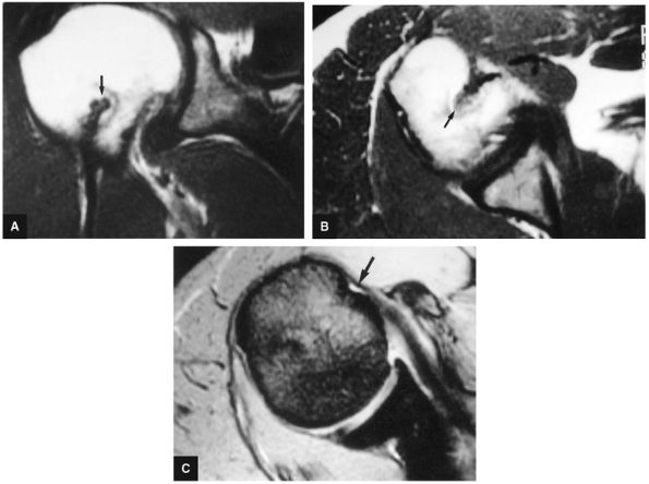 |
|
FIGURE 8.133 ● T1-weighted (A) coronal oblique and (B) axial images show biceps tenodesis (arrow). (C) The corresponding T2*-weighted axial image shows an absence of the biceps tendon in the bicipital groove (arrow).
|
-
Partial-thickness rotator cuff tears are articular, bursal, or interstitial (intrasubstance).
-
The PASTA lesion is a partial articular-sided supraspinatus tendon avulsion and corresponds to the articular surface delamination tears visualized on MR.
-
The bursal puddle sign of localized hyperintense fluid signal on coronal oblique MR images correlates with a bursal-side rotator cuff tear.
-
Intramuscular rotator cuff cysts communicate with partial- or full-thickness cuff tears.
-
Coronal images identify an intact stump of cuff tendon attaching to the greater tuberosity in cuff tears proximal to the tendinous footprint.
-
A wavy contour (“cuff wave sign”) of the retracted cuff tendon is associated with an easier cuff reattachment as the tissue is more compliant and less scarred.
-
Sagittal images are used to evaluate far anterior supraspinatus tendon tears.
-
Retracted rotator cuff tears are associated with an increase in cross-sectional diameter on sagittal images.
-
The normal (without atrophy) supraspinatus muscle nearly occupies the suprascapular fossa as assessed on sagittal images.
-
The biceps tendon may be medially subluxed or dislocated anteriorly, deep or within the substance of a torn distal subscapularis tendon.
-
Rotator cuff tendon retears may be associated with partial or complete tendon retraction and/or granulation tissue at the tear site simulating apparent cuff continuity.
-
A: At the articular surface
-
B: At the bursal surface
-
C: A complete tear, connecting A and B tears
-
0: Normal
-
I: Minimal superficial bursal or synovial irritation or mild capsular fraying in a small localized area (< 1 cm)
-
II: Fraying and failure of some rotator cuff fibers plus synovial bursal or capsular injury (< 2 cm)
-
III: Fraying and fragmentation of tendon fibers usually involving the whole surface of a cuff tendon, most commonly the supraspinatus (< 3 cm)
-
IV: Severe tear with tendon fraying, fragmentation, and a sizable flap tear involving more than a single tendon
-
Grade 1: Less than 3 mm deep
-
Grade 2: 3 to 6 mm deep and less than 50% of the cuff thickness involved
-
Grade 3: A high-grade partial tear more than 6 mm deep with more than 50% of the rotator cuff thickness involved
(Fig. 8.139). Partial articular surface tears occur more frequently than partial bursal surface or intrasubstance tears.144 Partial or incomplete tears are thought to be twice as common as complete or full-thickness tears of the rotator cuff.117 Partial tendon tears are distinct from muscle–tendon unit (MTU) strains. MTU strains demonstrate partial muscle group hyperintensity proximal to the conjoined tendon of the rotator cuff (Fig. 8.140). On coronal oblique MR images, partial tears demonstrate low to intermediate signal intensity on T1-weighted images, intermediate to high signal intensity on PD-weighted images, and bright signal intensity on conventional T2-weighted, T2-weighted FSE, and FS PD-weighted FSE sequences. Because severe degeneration and partial tears demonstrate similar regions of increased signal intensity on T2*-weighted images, we do not advocate the routine use of GRE sequences for the detection of rotator cuff disease.
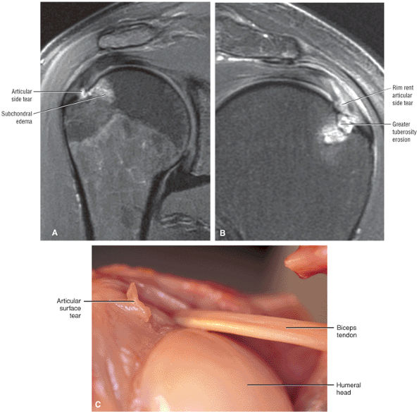 |
|
FIGURE 8.134 ● (A) Partial-thickness articular-side tear with adjacent osseous reaction on coronal FS PD FSE image. (B) Coronal FS PD FSE image illustrating a separate case of a rim rent partial articular-side cuff tear with adjacent greater tuberosity edema and erosion. (C) Articular surface irregularity on the undersurface of the cuff. The LHBT is intact. (From
Stoller DW. MRI, arthroscopy, and surgical anatomy of the joints. Philadelphia: Lippincott-Raven, 1999
, with permission.) |
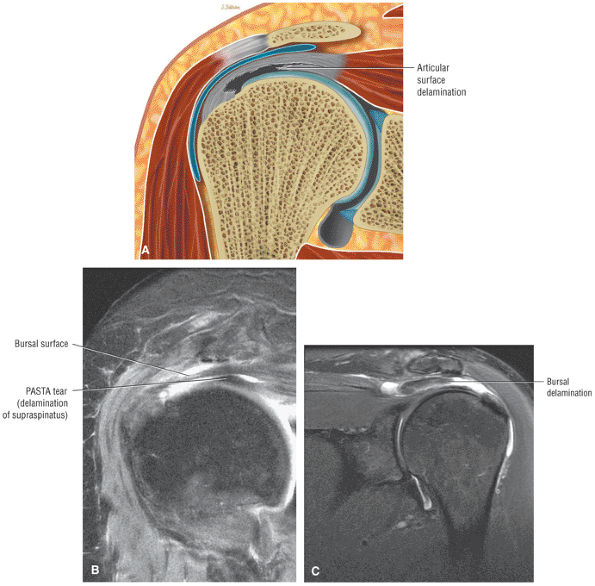 |
|
FIGURE 8.135 ● (A) Delamination of the articular surface of the rotator cuff that creates a substantial flap tear retracted from the remaining tendon is referred to as the PASTA (partial articular supraspinatus tendon avulsion) lesion. (B) PASTA tear with approximately 25% to 30% of the supraspinatus footprint still attached to the greater tuberosity. Retracted or avulsed articular surface fibers are retracted medially underneath the acromion. (C) A “reverse PASTA” involves partial bursal-side (rather than articular-side) delamination.
|
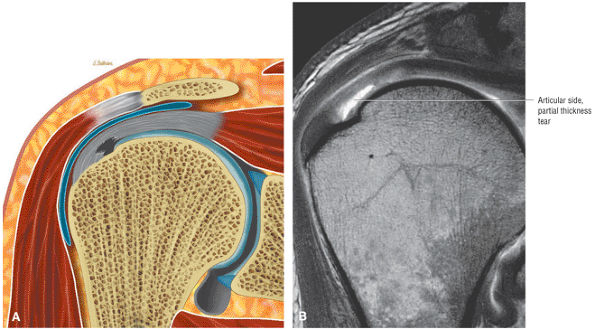 |
|
FIGURE 8.136 ● (A) Partial-thickness articular-side tear of the rotator cuff. (B) Intra-articular contrast extension into a partial-thickness tear of the rotator cuff.
|
The addition of fat suppression improves the visualization of the hyperintense fluid while suppressing the normal bright signal from fat.146 This technique helps to avoid mistaking areas of fat, especially linear streaks of fat, for gadolinium contrast extending into a partial tear site. The detection of partial articular surface tears can also be improved by using MR arthrography with the arm positioned in abduction and external rotation.147
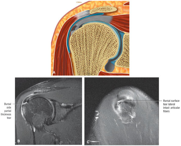 |
|
FIGURE 8.137 ● (A) Bursal surface partial-thickness rotator cuff tear. (B) High-grade or severe partial rotator cuff tear of the bursal surface. A sizable flap tear involving both the supraspinatus and conjoined portions of the cuff is demonstrated. (C) This sagittal image lateral to the articular fibers demonstrates fluid between torn bursal fibers and the greater tuberosity.
|
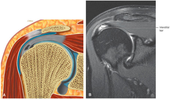 |
|
FIGURE 8.138 ● (A) Intrasubstance or interstitial tear of the supraspinatus without bursal or articular surface extension. (B) Coronal FS PD FSE image demonstrates the hyperintense interstitial tear without loss of continuity of the corresponding bursal or articular surfaces.
|
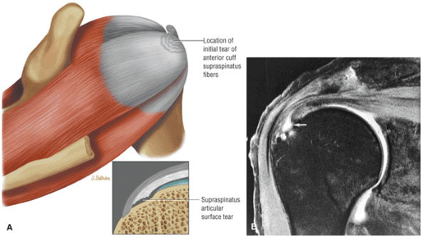 |
|
FIGURE 8.139 ● (A) Degenerative cuff pathology with initial failure of the rotator cuff occurring along the articular surface of the supraspinatus adjacent to its greater tuberosity insertion. (Based on
Matsen F III, Titelman R, Lippitt S, et al. Rotator cuff, Chapter 15. In: Rockwood CA Jr., Matsen FA III, Wirth MA, et al, eds. The shoulder, 3rd ed. Philadelphia: Saunders, 2004:791–878.
) (B) Partial articular surface tear (arrow) involving the conjoined portion of the rotator cuff. The bursal surface is intact and no fluid is identified in the subacromial-subdeltoid bursa. The tear is hyperintense on this FS PD-weighted FSE coronal (oblique) image. |
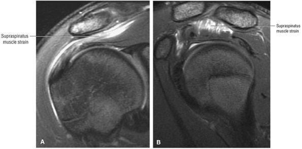 |
|
FIGURE 8.140 ● Superior surface muscle–tendon unit strain of the supraspinatus demonstrates hyperintense muscle edema superior to the tendinous expansion of the cuff on coronal FS PD FSE (A) and sagittal FS PD FSE (B) images.
|
frequently ruptured in chronic rotator cuff deficiency. As the rotator cuff defect propagates, the tear may destabilize the LHBT and involve the subscapularis tendon. Biceps pulley lesions are associated with medial displacement of the biceps tendon, especially when both the anterior articular surface of the supraspinatus tendon and superior deep fibers of the subscapularis tendon are involved (also see discussion on Biceps Pulley Lesions). Rotator cuff arthropathy develops with failure and abrasive contact between the chondral surface of the humeral head and the coracoacromial arch, causing degenerative joint disease.
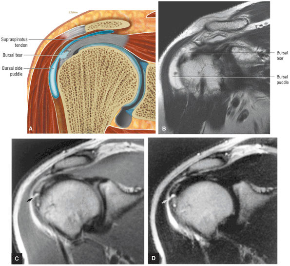 |
|
FIGURE 8.141 ● Bursal puddle sign associated with an adjacent bursal-side rotator cuff tear as seen on a color coronal section (A) and a coronal T2 FSE image (B). If this localized collection of subacromial fluid is identified without a full-thickness tear, then the diagnosis of bursal-side fraying or partial-thickness tear must be assumed. (C, D) A partial-thickness bursal surface tear (arrow) in communication with the subacromial-subdeltoid bursa. Fluid is hyperintense on intermediate weighted (C) and T2-weighted (D) FSE coronal oblique images.
|
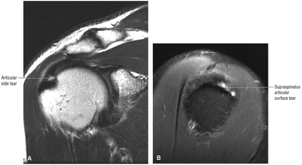 |
|
FIGURE 8.142 ● Partial-thickness articular surface tear requiring both coronal and sagittal images to assess the area of involvement (size of tear). (A) Coronal T2 FSE image. (B) Sagittal FS PD FSE image.
|
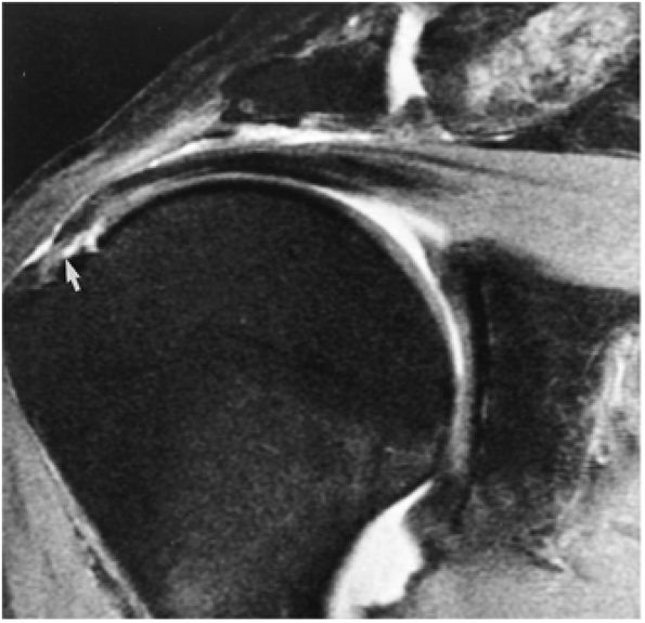 |
|
FIGURE 8.143 ● Partial tear with abnormal attenuation (arrow) of the distal conjoined supraspinatus and infraspinatus cuff tendons. Fluid is hyperintense and cuff degeneration is intermediate in signal intensity. There is no direct communication of fluid between the glenohumeral joint and subacromial-subdeltoid bursa on this FS PD-weighted FSE coronal oblique image.
|
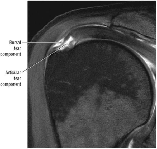 |
|
FIGURE 8.144 ● A complete tear connecting articular and bursal sides of the rotator cuff can be seen on this coronal FS T1-weighted MR arthrogram.
|
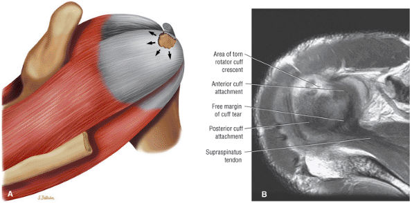 |
|
FIGURE 8.145 ● The notch phenomenon occurs when stress forces on the cuff tendon are directed toward the margin of the defect. Increased retraction forces result in further fiber failure, enlarging the area of the tear. (A) Posterosuperior view color illustration and (B) axial PD FSE image.
|
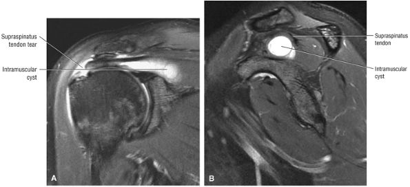 |
|
FIGURE 8.146 ● (A) Coronal FS PD FSE and (B) sagittal FS PD FSE images depict a hyperintense intramuscular cyst dissecting proximally into the supraspinatus muscle from the side of tendinous disruption.
|
-
Atrophy150
-
Fatty degeneration
-
Retraction
-
Loss of excursion
-
0: Tear lacks full-thickness communication between the bursal and articular surfaces, even if partial tears exist on both.
-
I: A small complete tear (puncture)
-
II: A moderate (< 2 cm) tear involving one tendon without retraction
-
III: A large (3 to 4 cm) complete tear involving an entire tendon with minimal retraction of the torn edge
-
IV: A massive cuff tear involving two or more cuff tendons, usually with associated retraction and scarring of the remaining tendon ends. Tears in this group may be subclassified or determined to be irreparable
-
Visualization of a tendon defect or tendinous gap, which is seen as an interruption or loss of continuity of the normally low-signal-intensity tendon
-
Tendon retraction, which is best assessed in the coronal plane. The torn cuff edge is located near the greater tuberosity insertion in stage 1 (Fig. 8.147), superior to the humeral head in stage 2 (Fig. 8.148), or retracted to the level of the glenoid margin in stage 3 (Fig. 8.149).
-
Joint fluid or granulation tissue at the cuff tear site, which is seen as areas of intermediate to increased signal intensity on T1-weighted and PD-weighted images. Depending on the complexity of the tear and the degree of retraction of the supraspinatus, a large fluid-filled gap may not be seen on sagittal images, especially if there is a delamination component to the cuff tear. Fluid signal appearing superior, anterior, and inferior along the undersurface of the supraspinatus tendon is characteristic of a complete tear (Fig. 8.150). On T2 spin-echo, T2-weighted FSE, and FS PD-weighted FSE sequences, these areas demonstrate markedly increased signal intensity.
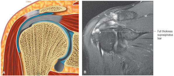 |
|
FIGURE 8.147 ● (A) Color coronal section and (B) coronal FS PD FSE image show a stage 1 full-thickness cuff tear with the torn cuff edge adjacent to the greater tuberosity.
|
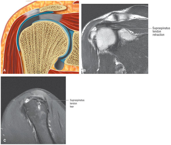 |
|
FIGURE 8.148 ● (A) Coronal color section, (B) coronal T2 FSE image, and (C) sagittal FS PD FSE image of a stage 2 full-thickness rotator cuff tear with supraspinatus tendon retraction superior to the humeral head.
|
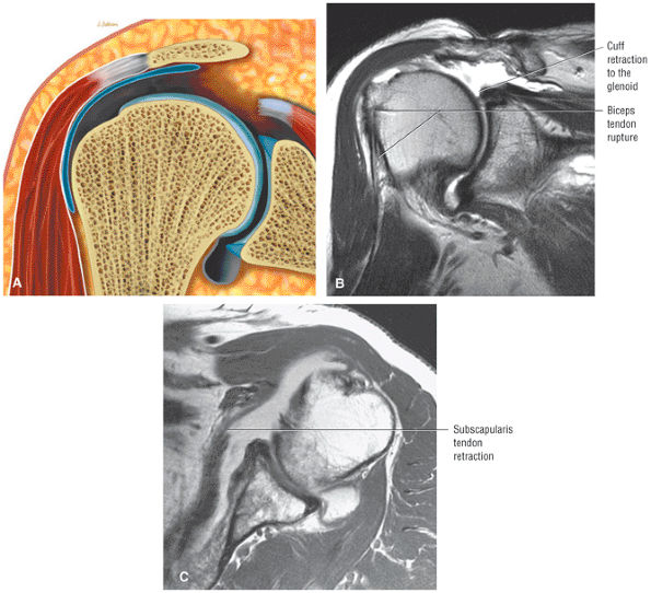 |
|
FIGURE 8.149 A ● Coronal color section, (B) coronal T2 FSE image, and (C) axial PD FSE image show a stage 3 full-thickness rotator cuff tear with tendon retraction to the level of the glenoid.
|
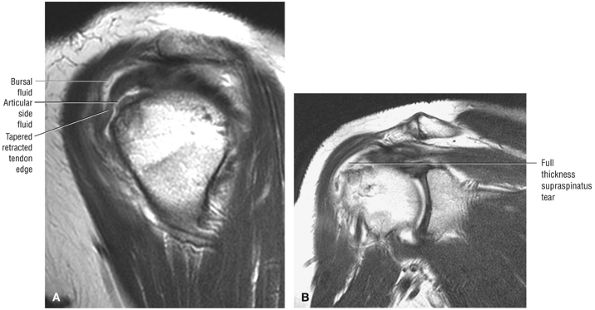 |
|
FIGURE 8.150 ● (A) Sagittal T2 FSE and (B) coronal FSE images display hyperintense fluid signal intensity surrounding the anterior, bursal, and articular surfaces of the anterior cuff.
|
oblique and axial plane images. The tendinous gap and high-signal-intensity fluid seen in large supraspinatus tendon tears can be shown on axial images superior to the glenohumeral joint.
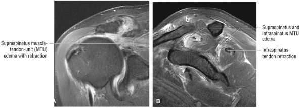 |
|
FIGURE 8.151 ● (A) Coronal FS PD FSE and (B) sagittal FS PD FSE images of hyperintense muscle–tendon signal intensity associated with a large full-thickness acute rotator cuff tear. There is secondary superior ascent of the humeral head.
|
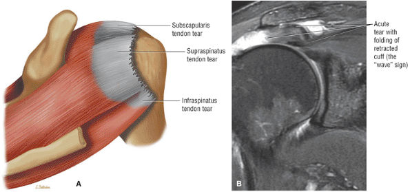 |
|
FIGURE 8.152 ● (A) Posterosuperior view color graphic showing a massive rotator cuff tear involving the supraspinatus, infraspinatus, and subscapularis tendons. (B) Coronal FS PD FSE image showing the wave sign of a retracted supraspinatus tendon as a sign of a reparable acute cuff tear without associated scarring.
|
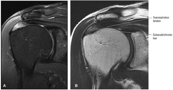 |
|
FIGURE 8.153 ● Coronal images depicting a nonacute supraspinatus tendon tear. The tears shows residual hyperintensity at the tear site on FS PD FSE images (A) and intermediate signal intensity on T2 FSE images (B).
|
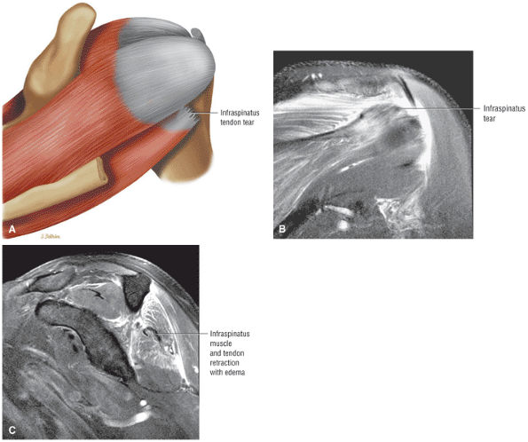 |
|
FIGURE 8.154 ● An isolated infraspinatus tendon tear shown on (A) a posterior superior color illustration, (B) a posterior coronal FS PD FSE image, and (C) a sagittal FS PD FSE image.
|
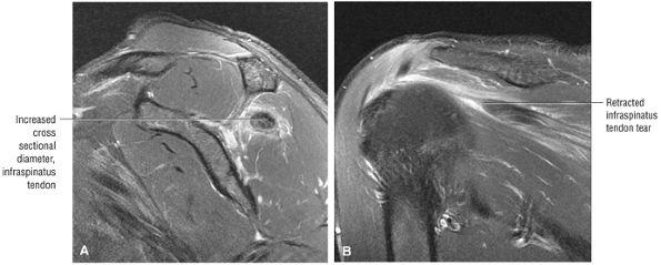 |
|
FIGURE 8.155 ● Increased cross-sectional diameter “sign” of a retracted infraspinatus tendon in an isolated tendon tear of the rotator cuff is seen on (A) sagittal FS PD FSE and (B) coronal FS PD FSE images. Increased tendon diameter is useful as a secondary sign of supraspinatus or infraspinatus tendon retraction.
|
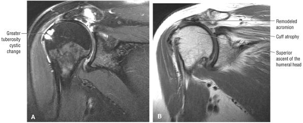 |
|
FIGURE 8.156 ● Coronal FS PD FSE (A) and T2 FSE (B) images showing chronic cuff arthropathy with superior ascent of the humeral head, contact and remodeling of the undersurface of the acromion, greater tuberosity cystic change, and fatty atrophy of the supraspinatus.
|
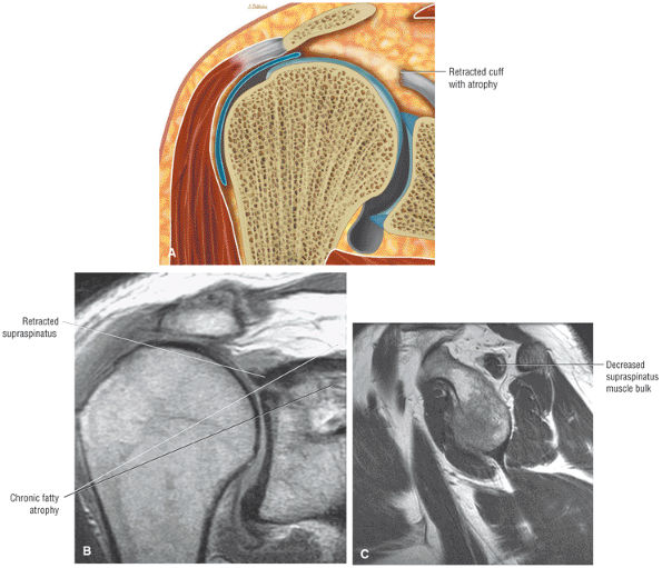 |
|
FIGURE 8.157 ● (A) Chronic rotator cuff fatty atrophy associated with proximal retraction. (B) Coronal PD FSE image showing supraspinatus atrophy with increased fat signal intensity superior to the retracted rotator cuff tendon. (C) Sagittal PD FSE image showing decreased supraspinatus muscle bulk with circumferential fat signal intensity extending from the supraspinatus fossa to the supraspinatus outlet.
|
-
Subacromial-subdeltoid bursal fluid, which should be readily identifiable, especially when there is a large volume of articular and bursal fluid associated with a complete tear. However, fluid in the subacromial bursa may also be present in impingement or in a partial bursal surface tear without communication with the glenohumeral joint. Subacromial-subdeltoid bursal fluid is also seen in asymptomatic individuals and in cases of isolated bursitis.117
-
Retraction of the supraspinatus musculotendinous junction may be seen in full-thickness cuff tears but is not observed with small cuff tears. The normal location of the supraspinatus musculotendinous junction is at approximately the 12 o—clock position, superior to the center of the humeral head. The location of this junction may vary within a 30° radius (15° either medial or lateral to the 12 o—clock position).116 The location of the musculotendinous junction may change with the position of the arm in internal or external rotation. Although this finding, even without a defined cuff defect, may indicate an increased probability for a tear, it is still a secondary finding.
-
Tears with granulation tissue may not demonstrate bright signal intensity on spin-echo or FSE T2-weighted images. However, these low-signal-intensity cuff tears may be identified by careful evaluation of tendon contour abnormalities and associated secondary signs of cuff disease.
-
Rarely a massive synovial reaction (hyperintense on FS PD FSE) may develop and fill the gap of a rotator cuff tear (Fig. 8.158). The biceps tendon may be difficult to find at surgery if it is encased in concentric layers of hypertrophied gelatinous synovium. Inflammatory arthropathy and even infection may present with similar imaging characteristics. Rice bodies (discrete synovial fronds) or subcutaneous edema, however, is not associated with this type of synovial response.
-
Subacromial and subdeltoid peribursal fat changes may also be considered secondary signs of cuff pathology. Because peribursal fat may be replaced by either low-signal-intensity granulation tissue or scar or bright-signal-intensity fluid, which is often limited to the site of the cuff tear, we use this abnormality as a secondary to tertiary sign when a cuff tear is not clearly visualized.
-
Fatty atrophy of the rotator cuff muscle is usually associated with more chronic complete tears. Fatty replacement is best demonstrated on T1- or PD-weighted images, which display high-signal-intensity (equal to fat) horizontal streaks parallel to the long axis of the supraspinatus. The changes of supraspinatus muscle atrophy are not conspicuous on GRE, FS PD-weighted FSE, or STIR sequences.
tears of the supraspinatus and infraspinatus tendons. How-ever, injury to the subscapularis may occur as an isolated partial tear independent of any other cuff pathology.154 Subscapularis tendon injuries range from small corner tears at the superior edge, adjacent to the bone tendon junction, to chronic massive retracted tears with fatty atrophy of the muscle (Fig. 8.161). Partial tears may be associated with thickening of the subscapularis tendon in conjunction with regions of fiber discontinuity.
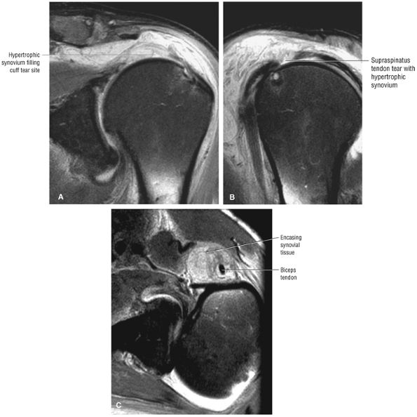 |
|
FIGURE 8.158 ● Hyperintense hypertrophic synovium occupying the tendinous gap of a full-thickness rotator cuff tear on a coronal FS PD FSE image (A) and sagittal FS PD FSE image (B). (C) The biceps tendon is encased in a massive thickened synovial envelope on this axial FS PD FSE image.
|
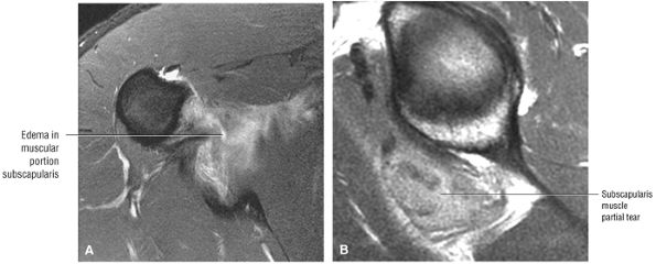 |
|
FIGURE 8.159 ● Inferior muscle belly partial tear of the subscapularis on (A) axial FS PD FSE and (B) sagittal PD FSE images.
|
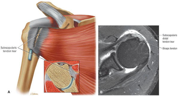 |
|
FIGURE 8.160 ● (A) Isolated subscapularis tendon tear without associated biceps tendon dislocation. (B) Subscapularis tendon tear with involvement of anterior or superficial fibers. Subscapularis tendon tears are associated with biceps tendon instability with laxity or disruption of the CHL–SGHL sling. SGHL tears are frequently associated with superior distal subscapularis tendon disruptions. Axial FS PD FSE image.
|
Because of the multipennate morphology of the subscapularis, the diagnosis of partial tears on sagittal images should always be confirmed in the axial plane.
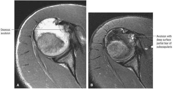 |
|
FIGURE 8.161 ● Axial PD FSE (A) and FS PD FSE (B) images showing a subscapularis tendon tear with deep fiber osseous avulsion from the lesser tuberosity in a wrestler.
|
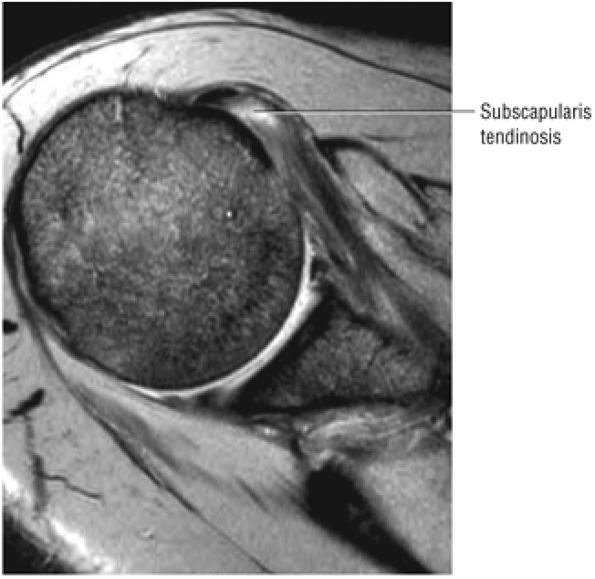 |
|
FIGURE 8.162 ● Degenerative fraying and tendinosis of the distal leading edge of the subscapularis tendon.
|
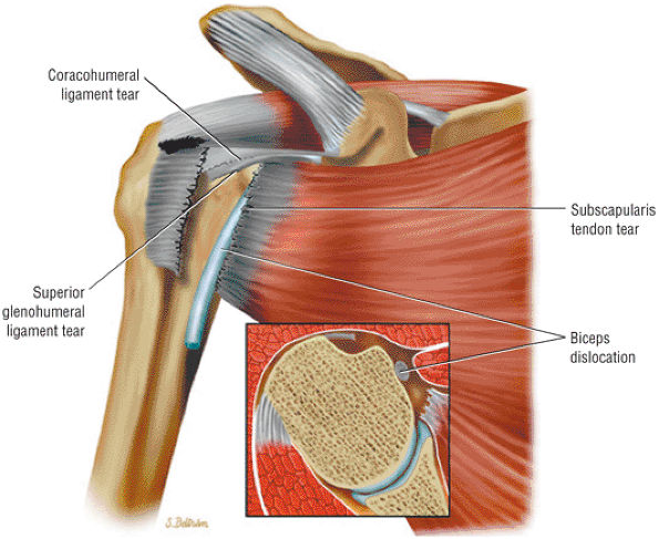 |
|
FIGURE 8.163 ● Biceps dislocation associated with rupture of the distal subscapularis tendon and tearing of the CHL–SGHL sling.
|
or strain is also more accurately displayed with greater conspicuity on FS PD FSE images (Fig. 8.167).
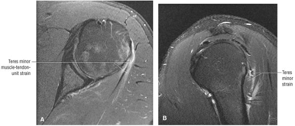 |
|
FIGURE 8.164 ● Isolated teres minor muscle–tendon unit overload/strain on (A) axial and (B) sagittal FS PD FSE images.
|
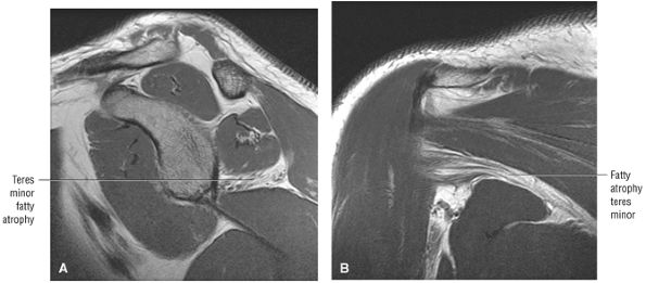 |
|
FIGURE 8.165 ● Isolated fatty atrophy of the teres minor muscle in quadrilateral space syndrome on (A) sagittal and (B) coronal PD FSE images.
|
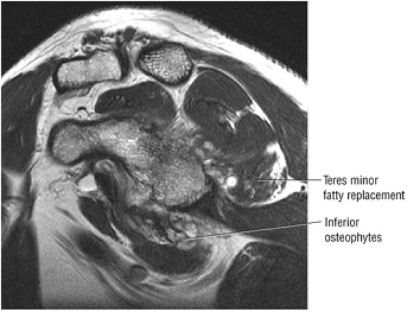 |
|
FIGURE 8.166 ● On this sagittal T2 FSE image, space-occupying inferior osteophytes associated with partial fatty replacement of the teres minor muscle are seen encroaching into the quadrilateral space.
|
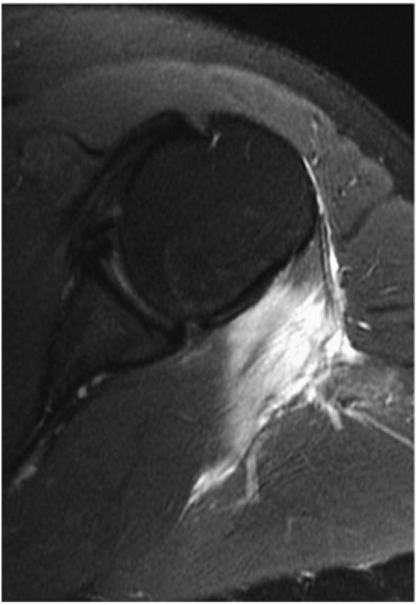 |
|
FIGURE 8.167 ● Infraspinatus myositis secondary to injection on an axial FS PD FSE image.
|
-
Persistent changes from impingement (including tendon degeneration, partial tear, and retear [Fig. 8.169], a rough undersurface of the acromion, or residual AC joint callus or osteophytes)
-
Deltoid attachment instability (Fig. 8.170)
-
Nerve damage
of fluid signal intensity on T2-weighted or FS PD-weighted FSE sequences is diagnostic for a retorn repair. A retracted or nonvisualized section of the rotator cuff also represents a full-thickness tear. Because rotator cuff contours may be irregular in the postsurgical cuff, the distinction between a partial-thickness tear and an intact repair site may be difficult. Owen et al.153 reported a 90% accuracy for the detection of full-thickness tears in the postoperative shoulder. Sagittal T2-weighted images are particularly useful in the evaluation of the anterior portion of the supraspinatus tendon. They minimize the partial volume effect of subacromial-subdeltoid fluid anteriorly and demonstrate portions of the cuff that may be difficult to discern on coronal oblique images because of a micrometallic or suture artifact.
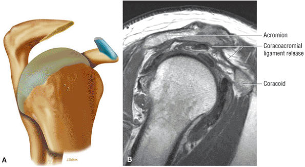 |
|
FIGURE 8.168 ● (A) Partial anterior acromioplasty. The coracoacromial ligament (CA) should be released from the acromion and not resected from under the deltoid in order to allow the ligament to reattach to the acromion and reconstitute the anterior arch. (B) Subacromial decompression performed for a partial-thickness rotator cuff tear. In cuff impingement the coracoacromial ligament is frayed and fragmented and associated with synovitis. Decompression results in a flat undersurface of the acromion and release of the CA ligament. The inferior lip of the distal clavicle is also removed if it extends inferior to the flattened acromion. Coplaning the distal clavicle avoids a step-off between the acromion and clavicle.
|
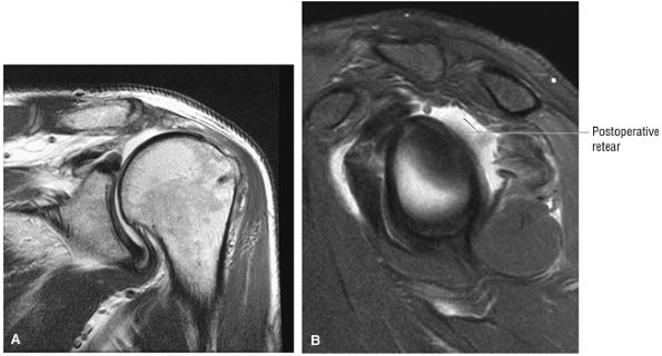 |
|
FIGURE 8.169 ● Massive retear of the rotator cuff tendons after repair. The retracted supraspinatus and infraspinatus tendons are shown on coronal PD FSE (A) and sagittal FS PD FSE (B) images.
|
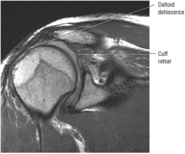 |
|
FIGURE 8.170 ● Postoperative deltoid avulsion. In the presence of a symptomatic AC joint, an undersurface claviculoplasty is performed, which protects and preserves the deltoid origin. Although these avulsions may not be painful, they can be repaired along with a re-repair of the cuff to allow the patient to lift the arm with a functioning deltoid.
|
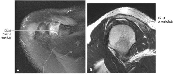 |
|
FIGURE 8.171 ● A Mumford or arthroscopic distal clavicle resection (ADCR) is performed for symptomatic AC joints. Coplaning or the “mini-Mumford” is also an option to remove inferior AC joint spurs. (A) Axial FS PD FSE and (B) axial T2 FSE images.
|
head articular cartilage and directed medial and inferiorly into subchondral bone. The deltoid-sparing aspect of the arthroscopic repair represents an advantage over open procedures. Postoperative inflammation usually resolves by 6 weeks. As mentioned above, postoperative MR examination should document healing of the repaired cuff with a reestablished supraspinatus tendon footprint over the greater tuberosity.169
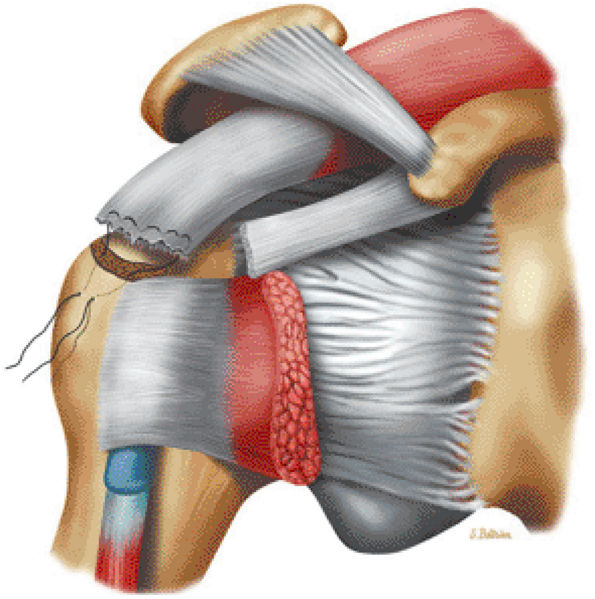 |
|
FIGURE 8.172 ● Tendon-to-bone rotator cuff repair with suturing of the edge of the distal cuff into a prepared humeral head trough.
|
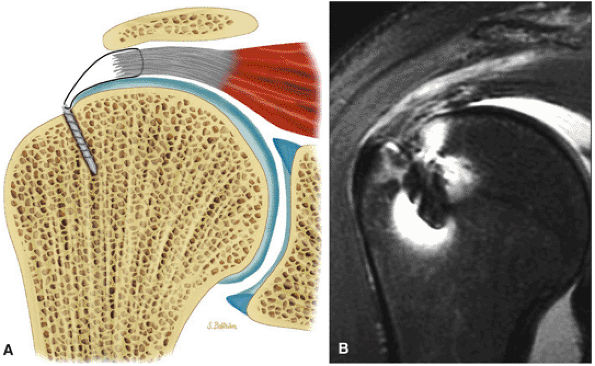 |
|
FIGURE 8.173 ● (A) The majority of torn rotator cuffs can be repaired arthroscopically. Suture anchor fixation of the rotator cuff tear to bone is shown. One or two sutures can be used in each suture anchor. The arthroscopic technique allows for an enhanced fixation of the cuff tendon, which can be performed with side-to-side suture anchors. (B) Coronal FS PD FSE image showing the suture anchors (two or three anchors may be needed) located lateral to the edge of the articular cartilage and directly obliquely and medial into subchondral bone. There is residual cuff tendinosis and subacromial bursal fluid.
|
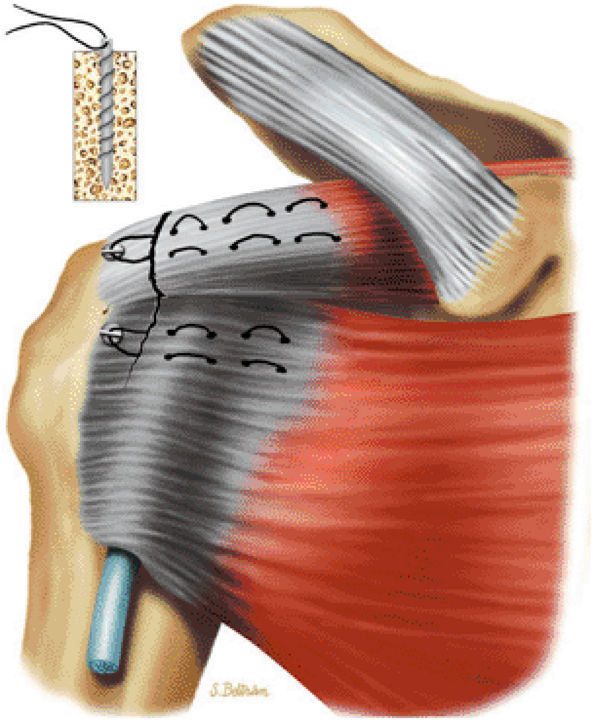 |
|
FIGURE 8.174 ● Suture anchor repair of both the supraspinatus and subscapularis tendons. Suture anchors do not preclude postoperative MR assessment. Arthroscopy spares damage to the deltoid and allows an ideal subacromial decompression.
|
-
The structures involved in microinstability include the biceps, the biceps pulley, the biceps root attachment, the rotator cuff, and the rotator cuff interval.
-
Microinstability does not refer to anteroinferior instability, but instead denotes pathologic conditions in the superior half of the shoulder.
-
Superior structures:
-
The biceps and its associated pulley (CHL and SGHL)
-
The biceps root attachment/superior labrum (SLAP lesions)
-
The rotator cuff
-
-
Anterior structures:
-
Rotator interval, including the SGHL in the anterior superior portion and the MGHL inferior to the SGHL
-
-
SGHL avulsion or laxity
-
MGHL avulsion producing straight anterior laxity
-
SLAP lesions (types 1–10). A type 10 SLAP lesion is a type 2 SLAP tear with extension into the rotator interval.
-
Posterior peel-back SLAP tears
-
Interval defects or biceps pulley lesions
-
Articular side cuff lesions (partial-thickness and typically non-crescentic in location). These articular side tears may occur from abrasion of the rotator cuff on the glenoid either anteriorly or posteriorly.
-
Rotator cuff tendinitis (tendinosis) or pain
-
A subjective feeling of slipping of the shoulder when not abducted and externally rotated. (This slipping is perceived by the patient as an abnormal or uncomfortable motion or laxity between the glenoid and humeral head.)
-
Easy fatigue of the shoulder muscles or parascapular pain
-
Impingement-like pain, which may mimic rotator cuff disease
-
The application of traction forces in the overhead position may produce a SLAP or SLAC lesion.
-
A seat belt across the involved shoulder (roll-around seat belt on impact) is associated with SLAC lesions.
-
A fall on the abducted arm is associated with the classic and SLAP variants.
-
“Throwing out” of the shoulder may produce a MGHL injury.
-
Overhead repetitive work or sports activity and professional throwing athletes may present with posterior peel-back SLAP with posterior superior instability due to glenohumeral internal rotation deficit (GIRD).
-
No trauma history may be associated with biceps pulley lesions.
and optimized signal-to-noise or MR arthrograms using the ABER position. MR examinations are important in identifying partial-thickness articular surface tears of the rotator cuff and peel-back lesions. MR examinations in microinstability include:
-
Posterior coronal images and sagittal and axial images display peel-back lesions with posterosuperior labral tears. Axial and sagittal images may further show an early pattern of eccentric sclerosis or wear as a pre-posterior peel-back lesion.
-
Coronal plane images are used to distinguish a type 2 or 3 BLC with a normal biceps labral sulcus from a SLAP lesion.
-
MR arthrography optimizes depiction of biceps pulley lesions, with improved appreciation of the degree of injury to the CHL and SGHL.
-
Non-contrast studies are satisfactory for characterization of gross subluxation of the biceps.
-
Partial-thickness articular surface tears are seen as a detachment of cuff fibers at their footprint attachment to the greater tuberosity both on ABER MR arthrograms and routine phased-array coil imaging of the shoulder.
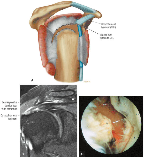 |
|
FIGURE 8.175 ● (A) Adherence of the retracted rotator cuff to the coracohumeral ligament. (B) Coronal FS PD FSE image showing the thickened coracohumeral ligament associated with torn and retracted supraspinatus. (C) A corresponding arthroscopic view shows the articular surface of the avulsed supraspinatus tendon (S; arrow). B, biceps tendon; HH, humeral head; Sub, subacromial space.
|
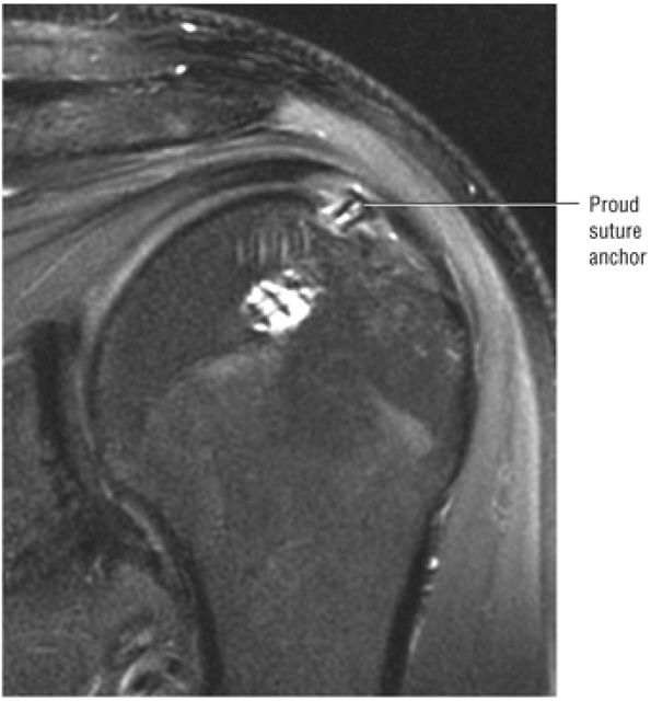 |
|
FIGURE 8.176 ● A coronal FS PD FSE image after rotator cuff repair shows a proud suture anchor superficial to the humeral head contour.
|
-
Superior labral detachment and extensions (synovial reaction and chondral erosions may be associated findings)
-
Capsular (SGHL and MGHL) tears and laxity
-
Laxity of the rotator interval
-
Non-crescentic articular-side partial-thickness rotator cuff lesions
-
The attachment of the CHL at the bicipital groove (lateral lip or greater tuberosity side) (the CHL is a bursal structure and cannot be visualized from the articular surface)
-
Biceps pulley lesions with either biceps subluxation on dislocation
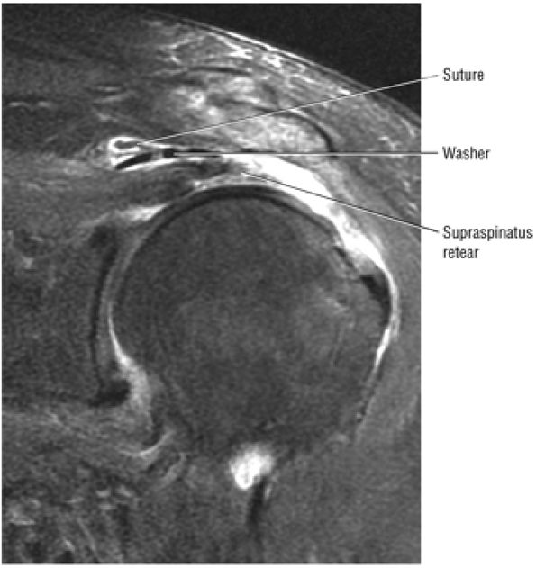 |
|
FIGURE 8.177 ● Coronal FS PD FSE image showing a cuff retear with subacromial displacement of a linear cuff washer with attached suture. The washer was used to gain greater cuff surface purchase.
|
-
The SLAC lesion is associated with an articular-side partial-thickness anterior supraspinatus tendon lesion.
-
The SLAC lesion is combined with the anterior component of a SLAP 2 tear.
-
The SLAC lesion is a type of instability and not an impingement lesion.
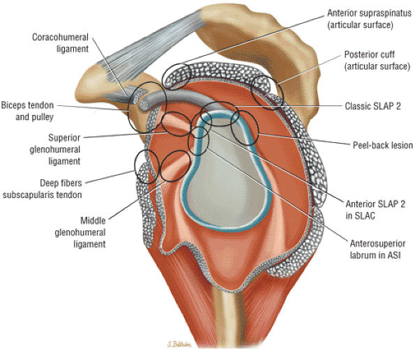 |
|
FIGURE 8.178 ● Potential sites of involvement in microinstability, including the anterior supraspinatus and anterior component of a SLAP 2 in the SLAC lesion; the posterior cuff and posterior component of a SLAP 2 in the posterior peel-back lesion; the classic anterior-to-posterior SLAP 2 lesion; anterosuperior impingement (ASI) involving the superior subscapularis, CHL–SGHL complex, the anterior supraspinatus and anterosuperior labrum, and the middle glenohumeral ligament (MGL) in anterior laxity.
|
-
The rotator interval is contained between the supraspinatus and subscapularis tendons.
-
The CHL is a bursal structure and the SGHL is an articular structure.
-
The confluence of the medial CHL and SGHL is an articular structure.
-
The confluence of the medial CHL and SGHL forms the biceps pulley within the rotator cuff interval.
-
Failure of the biceps pulley or sling is associated with medial subluxations and dislocations of the biceps tendon.
and the SGHL. The rotator interval contains a bursal layer and an articular layer:
-
The bursal layer of the interval is the CHL.
-
The articular layer of the interval is the SGHL.
-
The CHL and SGHL become confluent at their attachment to the greater and lesser tuberosities.
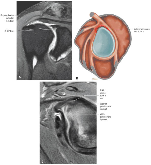 |
|
FIGURE 8.179 ● (A) Coronal FS PD FSE image of a SLAC lesion with partial articular-side supraspinatus tendon tear and anterior SLAP lesion. Sagittal color section (B) and FS PD FSE image (C) demonstrate labral separation of the anterior component of a SLAP 2 lesion.
|
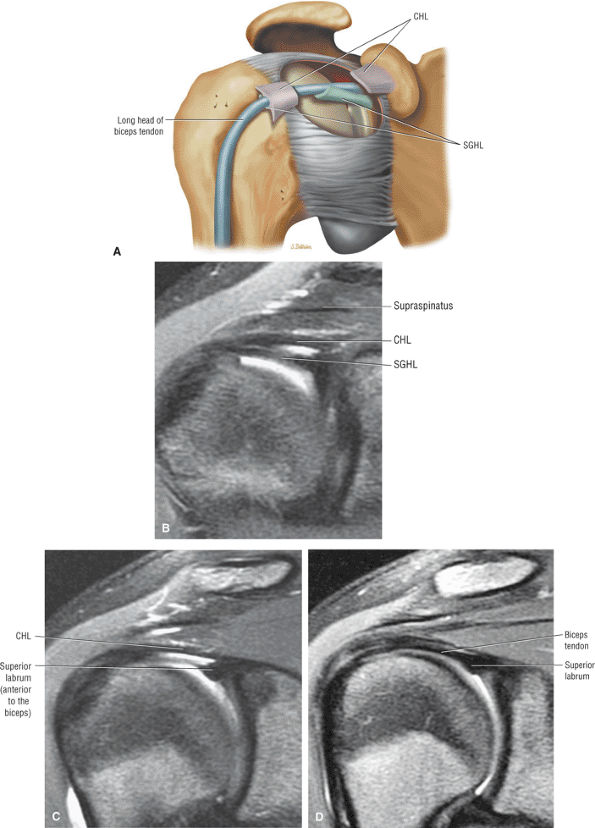 |
|
FIGURE 8.180 ● The rotator cuff interval, demonstrating the confluence of CHL and SGHL (SGL) to form the biceps pulley or sling at the entrance of the intertubercular groove. (A) The superior aspect of the glenohumeral joint capsule is windowed to reveal the contribution of the CHL to the roof and the SGHL to the floor of the biceps pulley. (Based on
Habermeyer P, Magosch P, Pritsch M, et al. Anterosuperior impingement of the shoulder as a result of pulley lesions: a prospective arthroscopic study. J Shoulder Elbow Surg 2004;13(1):5.
) Consecutive coronal oblique FS PD FSE images show the transition from the CHL and SGHL anteriorly (B) to the CHL one image posteriorly (C) and to the intra-articular biceps one more image posterior (D). The CHL (which forms the roof of the biceps pulley) and the SGHL (which forms the floor of the biceps pulley) are visualized anterior to the biceps in their proximal course through the rotator cuff interval. |
-
The anterior edge of the supraspinatus tendon at the superior edge
-
The superior edge of the subscapularis tendon at the inferior edge
-
The transverse ligament over bicipital groove at the apex
-
The humeral head cartilage at the floor
-
The capsule of the rotator interval at the roof
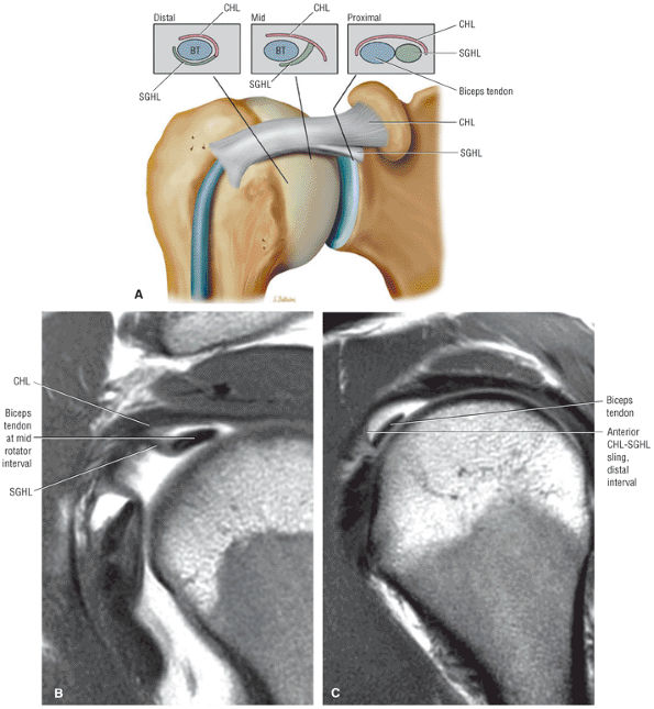 |
|
FIGURE 8.181 ● (A) Coronal 3D perspective of the rotator cuff interval. The formation of the biceps pulley or sling is shown from proximal, middle, and distal sections through the confluence of the CHL and SGHL. There is a T-shaped junction between the SGHL and CHL at the mid-interval, and a more U-shaped anterior sling is formed distally at the entrance of the intertubercular groove. A perpendicular junction between the SGHL and CHL medial to the formation of the more U-shaped biceps pulley developed in the distal portion of the rotator cuff interval. Corresponding sagittal PD FSE MR arthrograms, mid-interval (B) and distal interval (C).
|
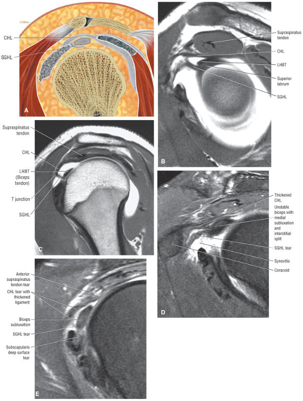 |
|
FIGURE 8.182 ● (A) Sagittal color section illustrating the proximal biceps pulley with the CHL forming the roof and the SGHL forming the floor, which envelops the LHBT. Note the T-shaped junction between the CHL/roof and the SGHL/floor at the level of the mid-rotator cuff interval. (B, C) Sagittal MR arthrograms of the proximal rotator cuff interval demonstrate the initial parallel course of the CHL and SGHL at the more lateral T-shaped junction of the biceps pulley formed between the CHL and SGHL at the mid-rotator cuff interval, superior to the medial humeral head. (D, E) Sagittal FS PD FSE images show comparison with complete disruption of the biceps pulley with abnormal laxity and thickening of the CHL–SGHL complex medially (D) and complete absence of the SGHL at the mid-rotator cuff interval in the expected location of the T junction between the CHL and SGHL (E).
|
 |
|
FIGURE 8.183 ● (A) The proximity of the CHL to the anterior border of the supraspinatus and its relationship to the SGHL and MGHL (MGL) are shown on this anterior coronal MR arthrogram. (B) CHL, SGHL, and intra-articular biceps are visualized on one image posterior to (A). (C) Coronal FS PD FSE image shows comparison in a separate case with a torn and medially retracted SGHL in the rotator cuff interval in a case of biceps instability and medial subluxation. (D) Coronal FS PD FSE image demonstrates discontinuity of the CHL in conjunction with an anterior supraspinatus.
|
-
Biceps pulley lesions are associated with tearing of the deep fibers of the distal subscapularis and articular surface of the distal supraspinatus tendon.
-
The medially dislocated biceps tendon is displaced either intra-articularly, between the coracohumeral ligament and the subscapularis tendon, or extra-articularly.
-
Intra-articular dislocation is associated with disruption of both the lesser tuberosity attachment of the subscapularis tendon and the SGHL–CHL complex.
-
Extra-articular subluxation is associated with an anterolateral supraspinatus tendon tear with extension into the lateral coracohumeral ligament.
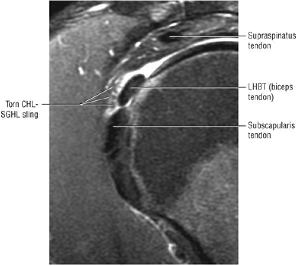 |
|
FIGURE 8.184 ● Type 1 (isolated) biceps pulley lesion with tear of the anterior CHL–SGHL sling shown on a sagittal FS PD FSE image. The articular surface of the supraspinatus and deep fibers of the subscapularis are intact.
|
of the SGHL–medial CHL complex. Tears of this complex may occur with or without associated tearing of the distal subscapularis tendon fibers and result in biceps tendon subluxation. This occult bicipital instability represents the hidden lesion described by Walch.178 The CHL normally inserts with the fibers of the subscapularis and traverses the intertubercular groove to contribute to the lateral aspect of the biceps sheath and supraspinatus. The medial CHL, the key anatomic portion, prevents medial subluxation of the biceps and contributes directly to the root and anterior superior aspect of the biceps tendon. The lateral CHL attaches more posteriorly to the greater tuberosity.
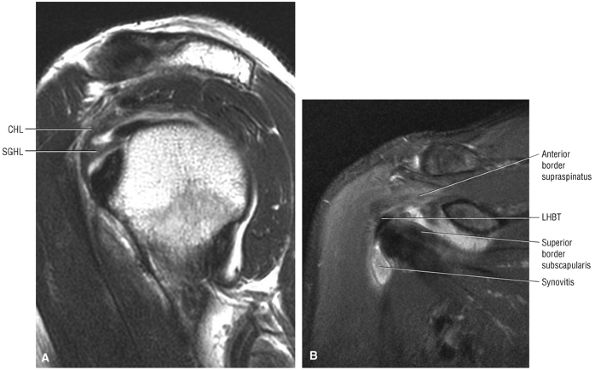 |
|
FIGURE 8.185 ● Thickened SGHL and CHL components of the biceps pulley seen at the mid-rotator interval on sagittal T2 FSE (A) and coronal FS PD FSE (B) images.
|
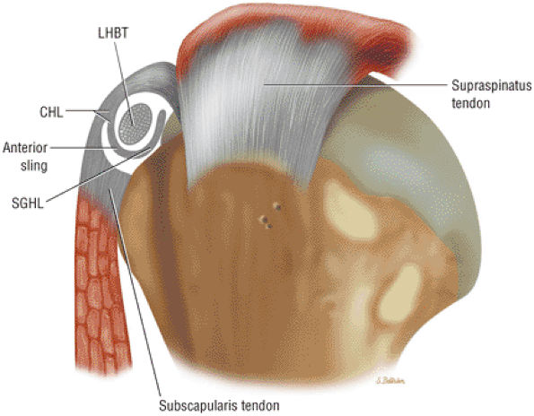 |
|
FIGURE 8.186 ● Biceps pulley formed by the CHL and SGHL. A 2D sagittal section of the subscapularis and a 3D perspective of the supraspinatus are shown in proximity to the pulley. Note the intimate relationship between the CHL (roof of the biceps pulley) and the anterior leading edge of the supraspinatus tendon. The medial CHL primarily contributes to the pulley, whereas the lateral CHL stabilizes the biceps (LHBT) through its attachment to the greater tuberosity. These lateral fibers are at a risk for injury with anterior and far lateral supraspinatus tears.
|
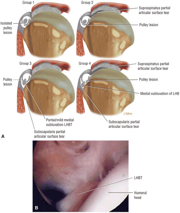 |
|
FIGURE 8.187 ● (A) The Habermeyer classification of biceps pulley lesions groups them into four subtypes. Type 1 lesions are isolated pulley lesions with an intact supraspinatus and subscapularis tendon. Type 2 represents a pulley lesion and a partial articular surface supraspinatus tendon tear. Type 3 is a pulley lesion with partial medial subluxation of the biceps tendon associated with a partial articular or deep surface tear of the superior distal fibers of the subscapularis tendon. Type 4 combines the pulley lesion with partial articular surface tears of both the supraspinatus and subscapularis tendons. There is frank medial subluxation of the LHBT as both the contributions of the CHL (roof of the sling) and SGHL (floor of the sling) are affected. (B) Arthroscopic view of type 3 biceps pulley lesion with disruption of the CHL–SGHL sling and medial subluxation of the biceps tendon associated with deep surface tearing of the subscapularis.
|
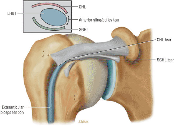 |
|
FIGURE 8.188 ● A type 1 biceps pulley lesion with a torn anterior CHL–SGHL sling. The biceps tendon (LHBT), although unstable, has not undergone subluxation.
|
-
A type 1 lesion is restricted or limited to an isolated surface of the pulley without involvement of the supraspinatus or subscapularis tendons (see Fig. 8.184; Fig. 8.188).
-
The type 2 pulley lesion involves articular side tearing of the supraspinatus tendon in association with pulley failure and mild medial subluxation of the biceps tendon.
-
The type 3 pulley lesion demonstrates partial deep surface tearing of distal subscapularis tendon fibers. The biceps undergoes medial subluxation, partially extending beyond the containment of the CHL–SGHL sling.
-
The type 4 lesion represents a dislocation of the biceps tendon (Fig. 8.189). In the type 4 lesion there is partial tearing of both the supraspinatus and subscapularis tendons in association with the medially displaced biceps tendon, which is located anterior to the lesser tuberosity. The supraspinatus and subscapularis tears are more extensive than those observed in type 2 and 3 lesions respectively.
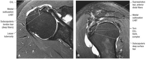 |
|
FIGURE 8.189 ● A type 4 biceps pulley disruption with biceps tendon medial subluxation anterior to the lesser tuberosity is shown on an axial FS PD FSE image (A) and sagittal FS PD FSE images from lateral to medial (B). Associated tears of both the supraspinatus and subscapularis are present.
|
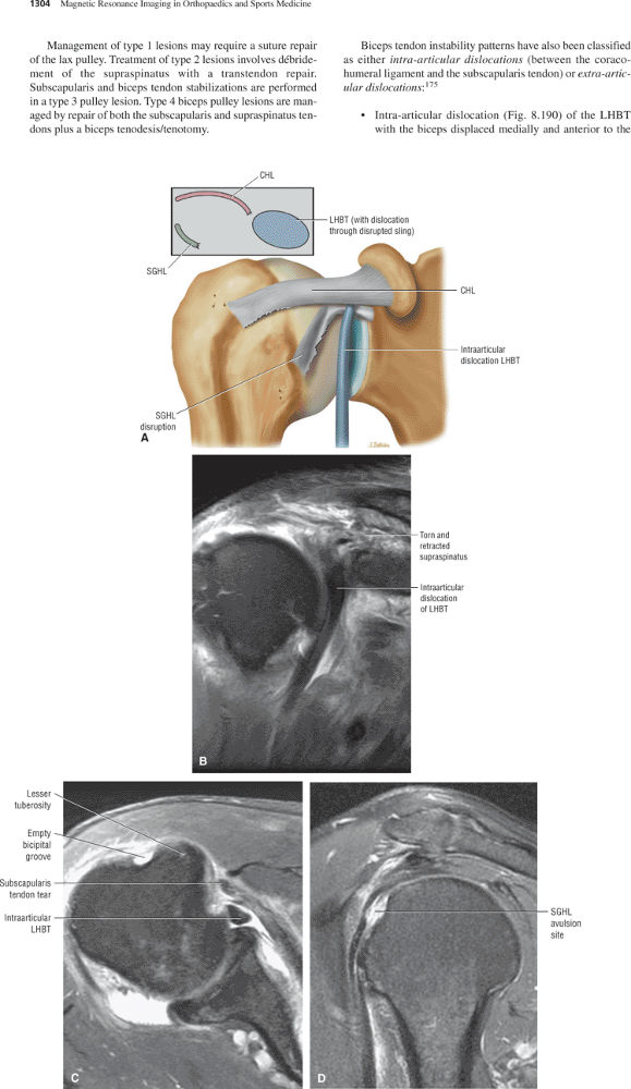 |
|
FIGURE 8.190 ● Intra-articular dislocation of the biceps tendon (LHBT) with complete disruption of the SGHL on a coronal color illustration (A) and on coronal (B) FS PD FSE images. Both the insertion of the subscapularis tendon and the SGHL component of the CHL–SGHL complex are disrupted. Intra-articular dislocation of the biceps tendon (LHBT) with complete disruption of the SGHL on a coronal color illustration on axial (C) FS PD FSE image. Both the insertion of the subscapularis tendon and the SGHL component of the CHL–SGHL complex are disrupted. (D) Sagittal FS PD FSE image in a separate case demonstrates avulsion of the SGHL attachment associated with an intra-articular biceps tendon dislocation.
|
-
Disruption of the SGHL–medial CHL complex with an intact lateral band (Fig. 8.191) of the coracohumeral ligament is associated with biceps subluxation anterior to the subscapularis but deep to the lateral band.
-
Extra-articular subluxation (Fig. 8.192) exists when there is an anterolateral supraspinatus tendon tear with extension into the lateral coracohumeral ligament. This permits the biceps tendon to subluxate in a medial direction (anterior to the lesser tuberosity), superficial to both the coracohumeral ligament and subscapularis tendon.
-
Delamination of the deep surface of the subscapularis (Fig. 8.193) produces injury to the SGHL–medial CHL complex. The biceps tendon is subluxated directly into the substance of the subscapularis tendon at the location of the delamination tear.
-
Anterosuperior impingement is associated with both a tear of the biceps pulley and involvement of the deep subscapularis tendon. A partial articular-side supraspinatus tear may coexist.
-
Anterosuperior labral tearing exists with decentralization of the humeral head occurring with adduction and internal rotation.
tendon impinge against the anterosuperior aspect of the glenoid rim (Fig. 8.195). The probability of ASI increases with subscapularis tendon involvement and secondarily with supraspinatus tearing. The addition of a partial articular-side tear or a lesion of the deep subscapularis to an existing pulley lesion is required for the development of ASI. A partial articular-side supraspinatus tear in the absence of subscapularis tendon involvement does not result in ASI. The frequency of an anterosuperior labral lesion as part of ASI is greater with the involvement of the biceps pulley, subscapularis, and supraspinatus (Fig. 8.196). Normally the LHBT is an anterior stabilizer of the glenohumeral joint during rotation of the arm. This anterior stabilizing effect on the glenohumeral joint is lost as the LHBT undergoes medial subluxation because of the pulley tear. The subluxation of the LHBT and decentralization of the humeral head represent the initial steps of the progressive cascade concluding in ASI. The superior fibers of the articular surface of the subscapularis are most frequently affected, and the tearing of deep fibers of the subscapularis is caused by the medial subluxation of the LHBT. Deep surface tears of the subscapularis tendon allow further anterior superior translation of the humeral head and potentiate ASI. The incidence of a symptomatic AC joint is higher in ASI, although the mechanism of injury has not been elucidated. There is also an association with symptomatic AC arthritis and posterior capsular injuries. We have observed an increased frequency of posterior SLAP 2 lesions and hypertrophic AC joints that demonstrate edema of the distal clavicle and adjacent acromion.
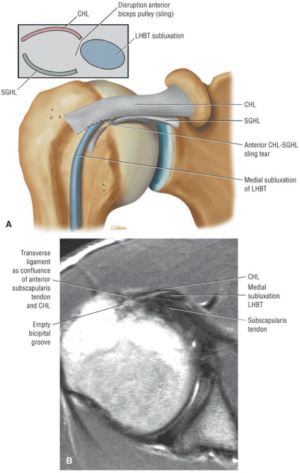 |
|
FIGURE 8.191 ● (A) Coronal color illustration showing medial subluxation of the biceps tendon anterior to the subscapularis tendon and deep to the CHL. This pathology is made possible by disruption of the anterior sling with intact lateral fibers of the CHL. The medial fibers of the CHL that directly contribute to the CHL–SGHL complex are torn in conjunction with the SGHL. (B) Axial PD FSE image showing medial subluxation of the biceps anterior to the subscapularis tendon and deep to the CHL.
|
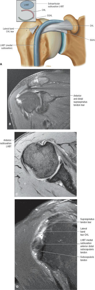 |
|
FIGURE 8.192 ● Extra-articular subluxation on (A) coronal color illustratio and, (B) coronal FS PD FSE image. The extra-articular subluxation is seen with the biceps perched anterior to the lesser tuberosity and anterior to both the coracohumeral ligament and the subscapularis tendon. The lateral band of the coracohumeral ligament is torn as a result of the anterior extension from an anterior and lateral supraspinatus tear. Extra-articular subluxation on (C) axial T2* GRE image. The extra-articular subluxation is seen with the biceps perched anterior to the lesser tuberosity and anterior to both the coracohumeral ligament and the subscapularis tendon. The lateral band of the coracohumeral is torn as a result of the anterior extension from an anterior and lateral supraspinatus tear. (D) Sagittal FS PD FSE image demonstrates disruption of the lateral fibers of the coracohumeral ligament in a separate case.
|
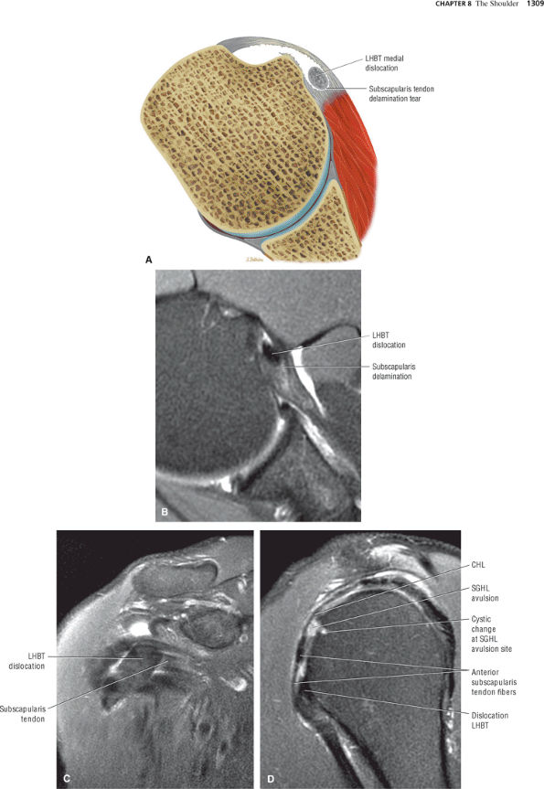 |
|
FIGURE 8.193 ● Dislocation of the biceps tendon (LHBT) directly into a delamination of the subscapularis tendon on (A) axial color illustration and (B) axial FS PD FSE image. Dislocation of the biceps tendon (LHBT) directly into a delamination of the subscapularis tendon on (C) coronal FS PD FSE image and (D) sagittal FS PD FSE image. The subscapularis tendon is visualized imbedded within the substance of the subscapularis tendon. An associated SGHL tear with reactive osseous erosion is shown in the sagittal plane (D).
|
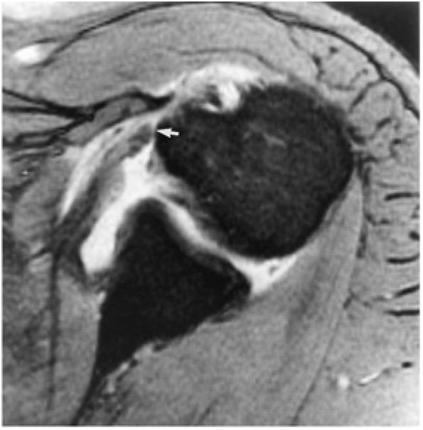 |
|
FIGURE 8.194 ● A T2*-weighted axial image illustrates a subscapularis tendon tear with proximal retraction (arrow) to the level of the lesser tuberosity. There is free communication of fluid between the glenohumeral joint subscapularis bursa and the subcoracoid bursa anterior to the subscapularis tendon.
|
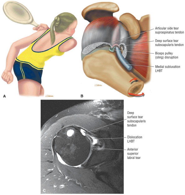 |
|
FIGURE 8.195 ● Anterosuperior impingement occurring with an internal rotation and adduction mechanism. Medial subluxation of the LHBT is associated with disruption of the biceps pulley system and partial tears of the articular surface of the subscapularis and supraspinatus tendons. Medial subluxation of the LHB causes the deep or articular surface tear of the subscapularis tendon. (A) Color graphic of a tennis player in position of shoulder adduction and internal rotation. (B) Superolateral view color illustration demonstrating the association of a grade 4 biceps pulley lesion and the corresponding pathomechanics of humeral adduction and internal rotation in anterosuperior impingement. (A, B: Based on
Habermeyer P, Magosch P, Pritsch M, et al. Anterosuperior impingement of the shoulder as a result of pulley lesions: a prospective arthroscopic study. J Shoulder Elbow Surg 2004;13(1):5.
) (C) An axial FS PD FSE image demonstrating biceps instability and an associated anterosuperior labral tear. There is tearing of the distal fibers of the subscapularis tendon. |
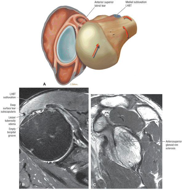 |
|
FIGURE 8.196 ● (A) Color graphic of the glenohumeral joint as viewed from a superolateral exposure with the humerus adducted and internally rotated. In anterosuperior impingement (ASI), an anterosuperior labral tear occurs as the humeral head migrates into the anterosuperior quadrant against the anterior glenoid rim. The normal posterior and compressive joint retraction function of the LHB is lost in ASI secondary to the unstable medially subluxed LHB. (Based on
Habermeyer P, Magosch P, Pritsch M, et al. Anterosuperior impingement of the shoulder as a result of pulley lesions: a prospective arthroscopic study. J Shoulder Elbow Surg 2004;13(1):5.
) (B) Axial FS PD FSE image shows ASI with medial subluxation of the biceps tendon, partial distal tearing of the subscapularis tendon, and an associated anterosuperior labral tear. (C) Corresponding sagittal PD FSE image with sclerosis of the anterior superior glenoid rim. |
-
A SLAP 2 or posterior SLAP 2 lesion causes the dead arm.
-
Repetitive tensile loading during follow-through results in a tight posterior band of the IGHL.
-
The tight posterior band bowstrings the humeral head in the late cocking phase, resulting in a posterosuperior shift of the glenohumeral contact point.
-
Glenohumeral internal rotation deficit (GIRD) is an acquired loss of internal rotation resulting from the tight posterior band of the IGL.
-
Peel-back posterior SLAP 2 lesions and posterior articular surface tears of the supraspinatus represent the net effect of the shift of the glenohumeral rotation contact point with a loss of internal rotation and gain of external rotation.
-
Pseudolaxity of the anterior IGHL results from a reduced cam effect of the proximal humerus, which allows for an even greater degree of external rotation.
-
On sagittal MR images, eccentric posterior glenoid rim sclerosis may precede the development of the peel-back labral lesion.
region of bare area of the humeral head were shown by Jin et al. to be lined with collagen and connective tissue and are connected to the joint space.187 Since internal impingement is a normal phenomenon, it is not surprising that humeral head cystic changes are seen in asymptomatic patients as a normal variation. These bare area cysts are more extensive in older elite throwers, and it appears that internal impingement becomes a pathologic process because excessive hyperexternal glenohumeral rotation produces abrasion of the cuff and bare area against the posterosuperior glenoid. Walch188 reported finding osteochondral lesions of the humeral head, superior to the classic Hill-Sachs lesion, that were less than 1 cm in size and only a few millimeters in depth. Although impaction on the posterosuperior glenoid was postulated, it could not be demonstrated at arthroscopy.188 In the younger throwing athlete the greater tuberosity usually has clearance over the posterosuperior glenoid rim through a greater arc of external rotation before internal impingement occurs.79 Hyperexternal rotation also results in repetitive hypertwisting of the rotator cuff fibers, causing torsional overload and shear failure of articular-side cuff fibers (Fig. 8.203). The external rotation proprioceptive set-point of high-level pitchers is referred to as “the slot,” and it allows for high-velocity throws of a baseball at speeds above 90 mph. The shift of the glenohumeral contact point with a tight posterior band of the IGHL allows the pitcher to more effectively externally rotate back to the set point.
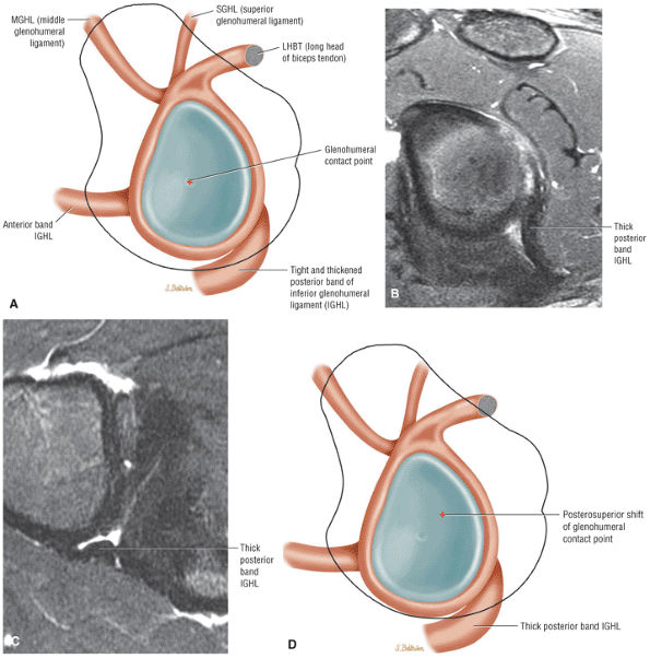 |
|
FIGURE 8.197 ● Initial steps of the pathologic cascade of changes in the throwing shoulder. (A) Abduction and external rotation with a tight and thickened posterior band of the inferior glenohumeral ligament. Thickened cross-section of the posterior band of the inferior glenohumeral ligament on sagittal (B) and axial (C) FS PD FSE images. (D) Posterosuperior shift of the glenohumeral contact point.
|
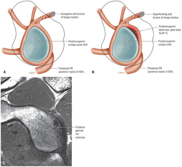 |
|
FIGURE 8.198 ● Dead arm with the development of a posterior SLAP 2 lesion. (A, B) Color illustrations of glenohumeral joint from lateral perspective. Hypertwisting and torsion of the intra-articular biceps are shown on (A), and a peel-back posterosuperior labral tear is shown on (B). (C) Sagittal PD FSE image of posterosuperior glenoid rim sclerosis associated with both the posterosuperior cam shift and the posterior SLAP 2 or peel-back lesion. The peel-back may extend to involve the posterior labrum contiguous with the posterosuperior quadrant.
|
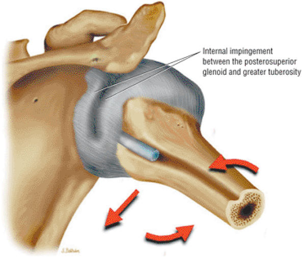 |
|
FIGURE 8.199 ● Internal impingement of the articular surface of the rotator cuff between the posterior superior glenoid and the greater tuberosity is appreciated as a normal mechanism in the position of shoulder abduction and external rotation. Therefore, internal impingement is usually not responsible for the pathologic cascade in the throwing shoulder.
|
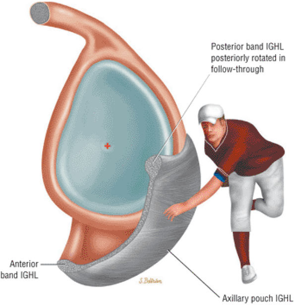 |
|
FIGURE 8.200 ● Repetitive tensile loading during the follow-through phase of throwing is the primary mechanism responsible for the development of the tight posteroinferior capsule. Large distraction forces must be resisted by the posteriorly rotated IGL during follow-through. (Based on
Burkhart SS, Morgan CD, Kibler WB. The disabled throwing shoulder: spectrum of pathology. Part I: Patho-anatomy and biomechanics. Arthroscopy 2003;19(4):404.
) |
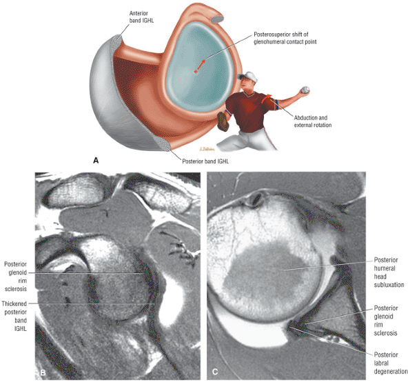 |
|
FIGURE 8.201 ● (A) A color graphic illustrating hyperabduction and external rotation in the late cocking phase of throwing. In the late cocking phase of throwing the posterior band of the IGHL is bowstrung underneath the humeral head, causing a posterosuperior shift in the glenohumeral contact or rotation point. An acquired tight or contracted posterior band of the IGHL thus initiates the pathologic cascade (evident in abduction and external rotation causing GIRD). A posterosuperior shift of the humeral head causes increased shear and peel-back forces to the posterosuperior glenoid labrum, increased greater tuberosity clearance, and scapular protraction. (Based on
Burkhart SS, Morgan CD, Kibler WB. The disabled throwing shoulder: spectrum of pathology. Part I: Pathoanatomy and biomechanics. Arthroscopy 2003;19(4):404.
) (B) The thickened posterior band of the IGL with mild posterior glenoid rim sclerosis in a baseball pitcher capable of throwing 100 miles an hour on a sagittal PD FSE MR arthrogram. (C) Corresponding posterior subluxation of the humeral head secondary to early changes of posterior glenohumeral wear and a tight posteroinferior capsule on an axial PD MR arthrogram. |
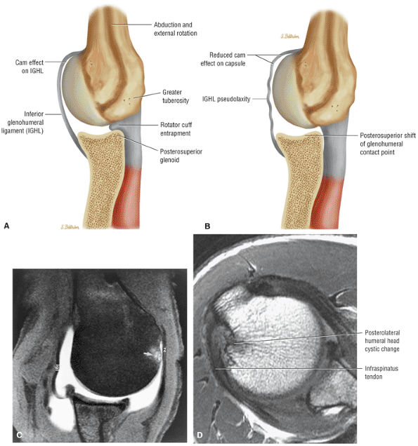 |
|
FIGURE 8.202 ● (A) Internal impingement, a normal phenomenon in all shoulders, is demonstrated with abduction and external rotation of the shoulder. The greater tuberosity abuts against the posterosuperior glenoid, which entraps the rotator cuff between these two osseous structures. In throwers the posterosuperior shift of the glenohumeral contact point produces a reduction of the cam effect as the space-occupying effect of the proximal humerus on the anteroinferior capsule (IGL) is reduced. (B) The resultant relative laxity (shown here) or redundancy of the IGL should not be misinterpreted as anteroinferior instability. Hyperexternal rotation of the rotator cuff results in repetitive hypertwisting with torsional overload and shear failure of cuff fibers. A partial-thickness articular surface tear then develops in the posterior supraspinatus or anterior infraspinatus tendon. (A, B: Based on
Burkhart SS, Morgan CD, Kibler WB. The disabled throwing shoulder: spectrum of pathology Part I: Pathoanatomy and biomechanics. Arthroscopy 2003;19(4):404.
) (C) Axial FS PD FSE image in abduction and external rotation confirms the relative laxity of the IGL and posterior shift of the humeral head. Note the proximity of the greater tuberosity to the rotator cuff. The nonarticular humeral erosion has been attributed to posterosuperior glenoid rim contact in internal impingement. (D) Axial PD FSE image of posterolateral humeral head cyst changes in a 30-year-old elite baseball player. The subchondral sclerosis and erosions are posterior to the greater tuberosity deep to the distal infraspinatus and involve the bare area of the humeral head. Associated posterosuperior glenoid rim remodeling is characteristic. |
-
A tight posterior band of the IGHL (a response to the follow-through phase of throwing)
-
GIRD
-
A posterosuperior shift in glenohumeral rotation point, which results in:
-
Increased clearance of the greater tuberosity over the glenoid
-
Reduced humeral head cam effect on the anterior inferior capsule
-
Hyperexternal rotation of the humerus relative to the scapula
-
-
Peel-back forces in late cocking phase, which cause a posterior type 2 SLAP lesion
-
Scapular protraction
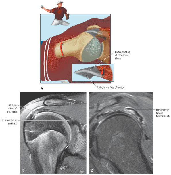 |
|
FIGURE 8.203 ● (A) Color coronal graphic of hyperexternal rotation during cocking phase of throwing, causing hypertwisting of the rotator cuff fibers. (Based on
Burkhart SS, Morgan CD, Kibler WB. The disabled throwing shoulder: spectrum of pathology. Part I: Pathoanatomy and biomechanics. Arthroscopy 2003;19(4):404.
) (B) Coronal FS PD FSE image with articular side-cuff hyperintensity and posterosuperior labral tear in a pitcher. (C) Sagittal FS PD FSE image in a separate case with posterior articular side-cuff overload. This may occur in the posterior supraspinatus or anterior portion of the infraspinatus. Hyperintensity is demonstrated in the infraspinatus musculotendinous junction tearing. |
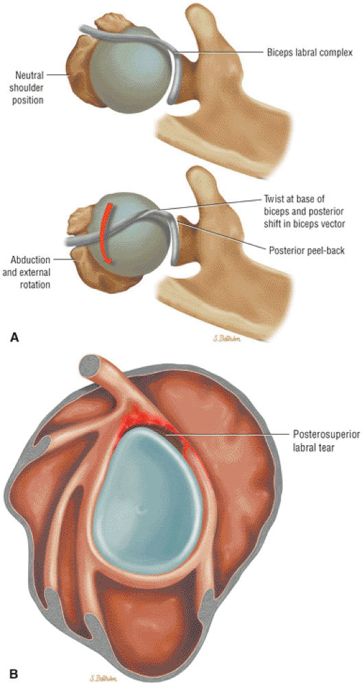 |
|
FIGURE 8.204 ● (A) Posterior superior view of the biceps labral complex at the resting position (top illustration). In abduction and external rotation there is a dynamic peel-back phenomenon as the biceps vector shifts posteriorly, with twisting at the base of the biceps (bottom illustration). (Based on
Burkhart SS, Morgan CD, Kibler WB. The disabled throwing shoulder: spectrum of pathology. Part I: Pathoanatomy and biomechanics. Arthroscopy 2003;19(4): 404.
) (B) Color illustration of glenoid labrum with lateral perspective. The peel-back mechanism is associated with either posterior SLAP 2 or combined anteroposterior SLAP 2 (classic SLAP 2) lesions. |
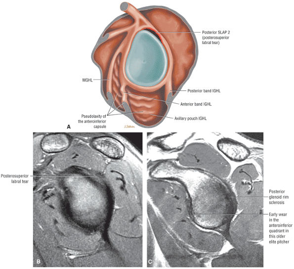 |
|
FIGURE 8.205 ● Pseudolaxity of the anterior inferior capsule secondary to a break in the labral ring associated with a posterior SLAP 2 lesion is shown on a sagittal color graphic (A) and a sagittal FS PD FSE image (B). (C) Moderate posterior glenoid rim sclerosis associated with mild anteroinferior rim sclerosis. The anteroinferior rim changes may be the initial changes of anteroinferior labral injury in the older elite pitcher or may be anterior rim wear secondary to pseudolaxity of the anteroinferior capsule.
|
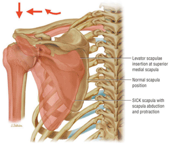 |
|
FIGURE 8.206 ● SICK scapula associated with scapular abduction and protraction. Tension on the superomedial scapular insertion of the levator scapulae produces a painful tendinopathy between the medial angle and root of the scapular spine. (Based on
Burkhart SS, Morgan CD, Kibler WB. The disabled throwing shoulder: spectrum of pathology. Part III: The SICK scapula, scapular dyskinesis, the kinetic chain, and rehabilitation. Arthroscopy 2003;19(6): 641.
) |
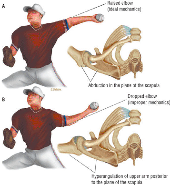 |
|
FIGURE 8.207 ● (A) Proper throwing mechanics with abduction of the arm in the plane of the scapula. Note the upper arm is maintained above the horizontal plane with the elbow positioned high. (B) Improper mechanics with a dropped elbow position and hyperangulation of the upper arm (humerus) posterior to the plane of the scapula. (Based on
Burkhart SS, Morgan CD, Kibler WB. The disabled throwing shoulder: spectrum of pathology. Part III: The SICK scapula, scapular dyskinesis, the kinetic chain, and rehabilitation. Arthroscopy 2003;19(6):641.
) |
-
The IGHL can fail at its attachment to the inferior pole of the glenoid (Bankart), mid-ligament, or at the attachment to the anatomic neck of the humerus (HAGL).
-
Bankart, Perthes, ALPSA, and HAGL lesions may all produce anterior instability.
-
The Bankart lesion may be osseous or primarily soft tissue.
-
Atraumatic anterior instability is a component of multidirectional instability (MDI).
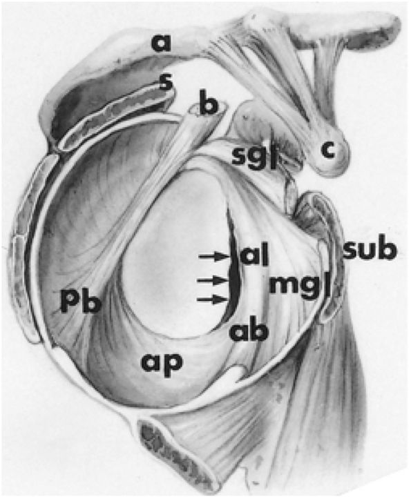 |
|
FIGURE 8.208 ● Anterior labral avulsion from the anterior glenoid rim (arrows). a, acromion; ab, anterior band of inferior glenohumeral ligament; al, anterior labrum; ap, axillary pouch of inferior glenohumeral ligament; c, coracoid; pb, posterior band of inferior glenohumeral ligament; s, supraspinatus tendon; sgl, superior glenohumeral ligament; sub, subscapularis tendon; b, biceps tendon; mgl, middle glenohumeral ligament.
|
-
Tightening of the anterior structures to limit external rotation (Magnuson-Stack and Putti-Platt procedure) (Fig. 8.212)
-
Coracoid transfer procedures (Bristow operation) to provide a bony block and a tenodesis effect to prevent anterior translation of the humeral head over the anterior glenoid rim
-
Osteotomies of the glenoid or humerus
-
Reconstruction of the avulsed or stretched IGLC structures (Bankart procedure and its modifications)
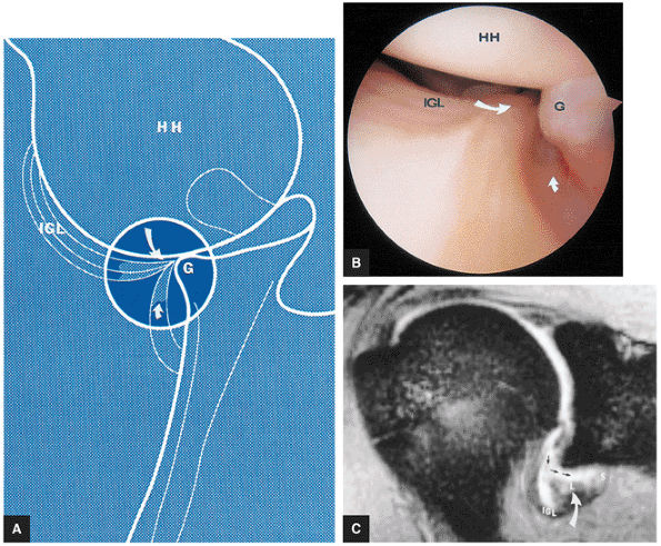 |
|
FIGURE 8.209 ● Bankart lesion. (A) A tear (large curved arrow) of the inferior glenoid and labral attachment of the inferior glenohumeral ligament (IGL) is present. Scarred muscle of the subscapularis is shown along the inferior glenoid neck (small curved arrow). The humeral head (HH) is subluxed inferiorly. G, glenoid. (B) The arthroscopic view from inferior to anterior is seen with the scope in the axillary pouch, oriented toward the anterior inferior pole of the glenoid. Note the avulsed labrum from the glenoid rim (G) and torn inferior pole attachment (large curved arrow) of the IGL. HH, humeral head. Scarred tearing of subscapularis muscle from the scapular neck is also identified (small curved arrow). (C) Avulsed anterior glenoid labrum (L; curved arrow) and IGL attachment are shown on a T2*-weighted coronal oblique image. Fluid extension (straight arrows) is identified between the inferior glenoid neck, detached labrum, and subscapularis muscle (S).
|
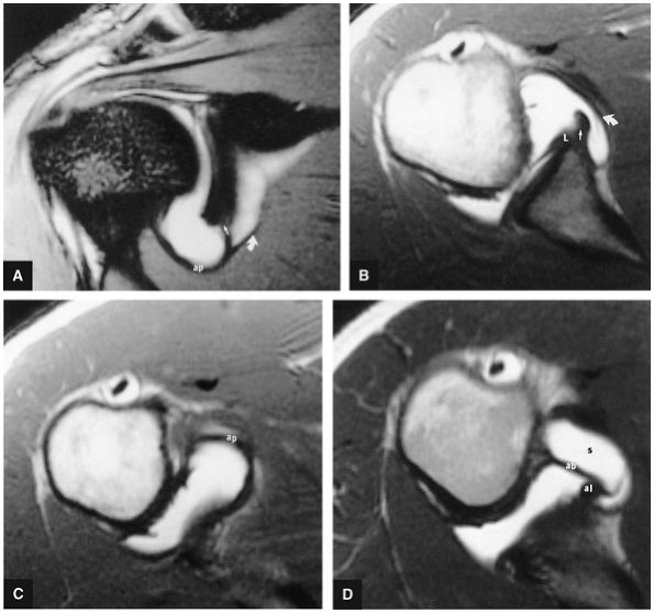 |
|
FIGURE 8.210 ● Inferior glenohumeral ligament labral complex. (A) Enhanced T2*-weighted GRE coronal oblique images demonstrate the normal inferior glenoid pole attachment of the axillary pouch (ap) of the inferior glenohumeral ligament (straight arrow). Note gadolinium contrast in normal inferior extension of subscapularis bursa (curved arrow). (B) An enhanced T1-weighted axial image displays the subscapularis bursa (curved arrow) and glenoid origin (straight arrow) of the inferior glenohumeral ligament complex (IGLC). The IGLC may originate from the glenoid, the labrum (L), or the neck of the glenoid immediately adjacent to the labrum. There is no anterior lateral tear on this image. (C) An enhanced T1-weighted axial image below the level of the glenoid displays the normal axillary pouch (ap) of the inferior glenohumeral ligament. (D) An enhanced T1-weighted axial image in a different patient identifies the anterior band (ab) of the IGLC and its continuation as the anterior labrum (al). Gadolinium contrast is shown in the subscapularis bursa (s) anterior to the anterior band. There is no tear of the anterior inferior labrum.
|
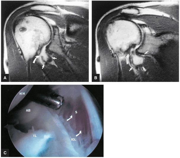 |
|
FIGURE 8.211 ● (A, B) Anterior coronal oblique images display an abnormally capacious axillary pouch (straight arrows) secondary to avulsion of the IGL humeral insertion (curved arrows). (C) An arthroscopic image also shows the avulsed humeral attachment of the IGL (curved arrows). AB, anterior band; HH, humeral head; IL, torn inferior labrum; S, subscapularis muscle.
|
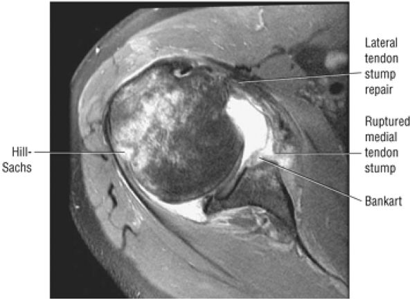 |
|
FIGURE 8.212 ● Axial FS PD FSE image showing a failed Putti-Platt with recurrent anterior instability and deficiency of the anterior inferior glenoid rim. In the Putti-Platt procedure the subscapularis tendon is divided. The lateral stump of the subscapularis is attached to soft tissue along the anterior rim of the glenoid and the medial stump is lapped over the lateral stump to the greater tuberosity to effect shortening of the capsule and subscapularis muscle.
|
-
Anterior rim glenoid fracture (>20%)
-
Large posterior humeral head defect
-
Severe ligament damage (previous capsular shrinkage with failure or HAGL lesion)
-
First-time traumatic dislocations, such as Hill-Sachs, Bankart, or Perthes lesions, without hyperlaxity
-
Recurrent posttraumatic dislocation with or without hyperlaxity
-
Injuries not involving compromise of IGHL and MGHL competence
-
Injuries without osteochondral lesions
-
Symptomatic subluxation
-
Osseous or bony Bankart lesions
-
Labral hypoplasia
-
Severe injury of the IGHL or MGHL
-
HAGL lesions
-
Injuries with concomitant cuff lesions
-
Voluntary instability and multidirectional instability
-
Posterior instability
-
Nondisplaced fracture of the greater tuberosity
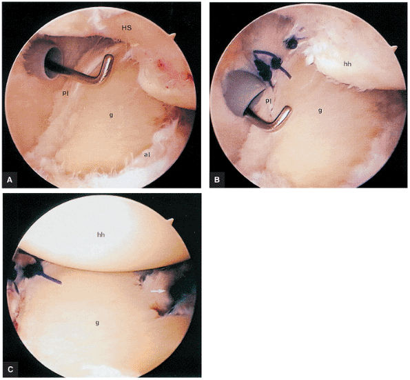 |
|
FIGURE 8.213 ● Arthroscopic repair of the anterior and posterior labrum help centralize an anteriorly dislocated humeral head as viewed from the level of the biceps tendon. (A) Frayed posterior labrum (pl) and anterior labrum (al) associated with a Hill-Sachs (HS) fracture of the humeral head are identified. g, glenoid. (B) Repair begins with the posterior inferior capsule sutured to the posterior labrum (pl). hh, humeral head; g, glenoid. (C) Anteriorly placed sutures (arrow) complete the arthroscopic stabilization centralizing the humeral head (hh) on the glenoid (g).
|
-
Subglenoid
-
Subclavicular
-
Intrathoracic
-
Retroperitoneal
-
Avulsion of the anterior inferior glenohumeral ligament (AIGHL) and capsule from the glenoid (more common in younger individuals)
-
HAGL lesion with or without bone flecks
-
Fractures of the glenoid, humeral head, tuberosities, or coracoid process
-
Cuff tears associated with anterior and inferior glenohumeral dislocation (30% incidence in patients less than 40 years of age and 80% incidence in patients over 60 years of age)
-
Vascular injury, which may occur during dislocation or reduction and is more common in elderly patients. The structures at risk include the axillary artery or vein or branches of the axillary artery—the thoracoacromial, subscapular, circumflex, and less commonly the long thoracic.
-
Neurovascular injuries, usually affecting the brachial plexus and axillary nerves
-
In soft tissue Bankart lesions (Fig. 8.216), the anteroinferior labrum is avulsed without fracture, deformity, or blunting of the anteroinferior glenoid rim. There may be only minimal subchondral edema of the anteroinferior glenoid.
-
The osseous or bony Bankart lesion (Fig. 8.217) presents with a small to large anterior inferior glenoid rim fracture that may extend anterior and superior to the equator.
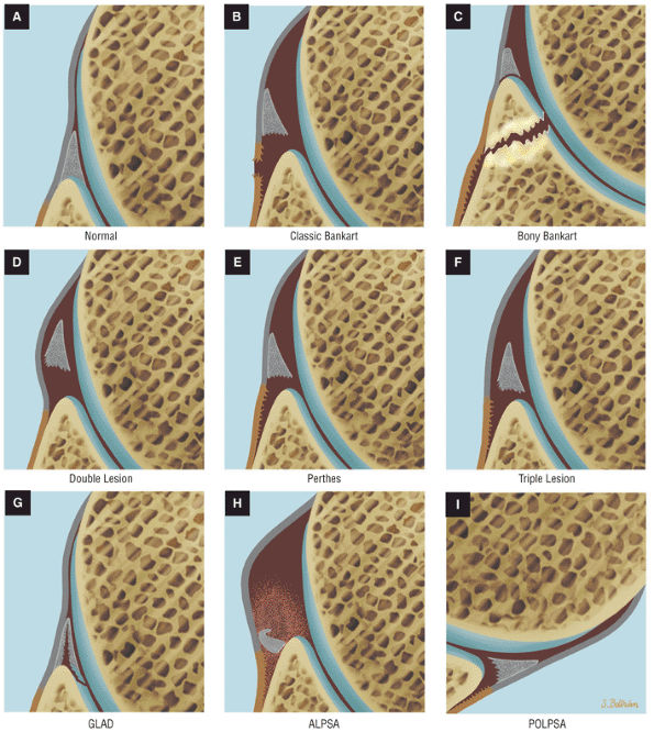 |
|
FIGURE 8.214 ● (A) Normal anterior inferior labrum and capsule. (B) Classic or soft tissue Bankart with disruption of scapular periosteum. (C) Bony or osseous Bankart with a double labral lesion. (D) Double labral lesion with labral disruption from both the glenoid rim and adjacent IGHL. (E) Perthes avulsion of the labrum and IGHL from the anterior scapular neck without periosteal disruption. (F) Triple labral lesion with disruption of the labrum from the glenoid rim and IGHL, with additional tearing of the IGHL from the scapular neck. (G) A GLAD lesion (glenoid labrum articular disruption) is also known as a GARD lesion (glenoid articular rim divot). These lesions involve a partial tear of the anterior inferior glenoid labrum with adjacent articular cartilage defect in clinically stable patients. (H) The ALPSA lesion is an anterior labroligamentous periosteal sleeve avulsion. (I) The POLPSA lesion (posterior labrocapsular periosteal sleeve avulsion).
|
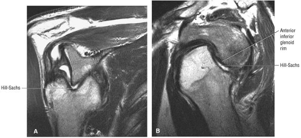 |
|
FIGURE 8.215 ● (A) Coronal and (B) sagittal T2 FSE images showing fixed anterior subcoracoid dislocation with a large posterolateral humeral head Hill-Sachs fracture.
|
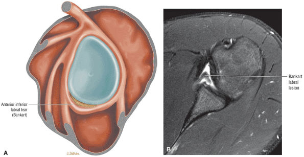 |
|
FIGURE 8.216 ● (A) Sagittal color graphic illustrating a soft tissue Bankart lesion. (B) Axial FS PD FSE image of anterior displaced anterior inferior labrum (Bankart lesion).
|
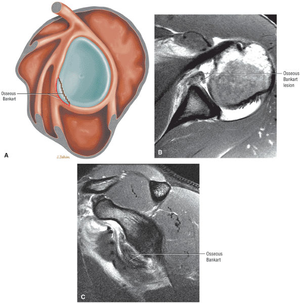 |
|
FIGURE 8.217 ● (A) Sagittal color graphic illustrating an osseous Bankart lesion. (B) Axial PD FSE MR arthrogram shows an anteroinferior osseous Bankart with avulsion of the labrum and involvement of the anterior glenoid rim. (C) Sagittal FS PD FSE MR arthrogram shows the extent of an anteroinferior glenoid rim fracture from the equator to the inferior pole.
|
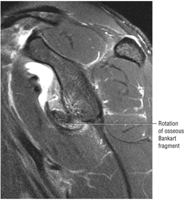 |
|
FIGURE 8.218 ● Sagittal FS PD FSE image demonstrates rotation of an anteroinferior osseous Bankart fracture.
|
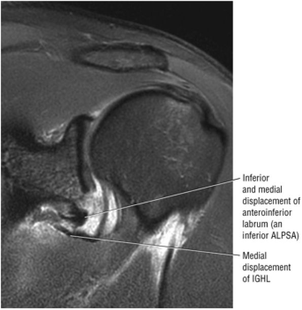 |
|
FIGURE 8.219 ● Coronal FS PD FSE image displays medial displacement of the anterior inferior labrum and axillary pouch of the IGHL in a Bankart lesion.
|
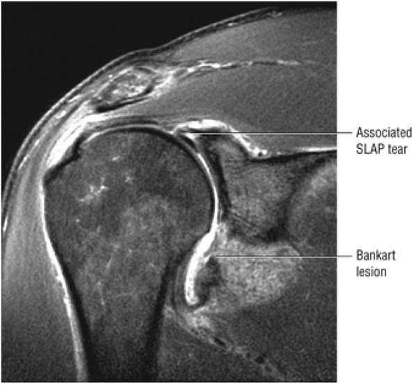 |
|
FIGURE 8.220 ● Coronal FS PD FSE image showing a SLAP 5 lesion. A type 5 SLAP is a combination of a type 2 or 3 SLAP and a Bankart lesion.
|
avulsed labrum, when it occurs, is secondary to medial and inferior pull from the anterior band of the IGHL. A linear area of hyperintensity is seen in the area of stretching or plastic deformation across the axillary pouch of the IGHL. This is better visualized with the arm positioned in abduction and external rotation to tighten the IGHL complex.
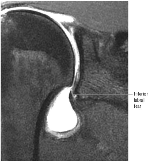 |
|
FIGURE 8.221 ● In the absence of the rare circumferential meniscoid labral variant, no contrast should extend between the inferior labrum and adjacent glenoid articular cartilage. Coronal FS PD FSE image.
|
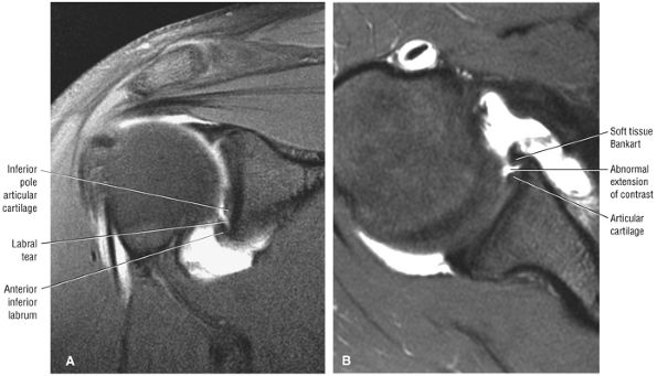 |
|
FIGURE 8.222 ● Soft tissue Bankart lesion on coronal (A) and axial (B) FS PD FSE images. Note detection of contrast between the inferior labrum and glenoid inferior pole articular cartilage on the coronal image (A). An anteroinferior labral tear can be seen at the inferior glenoid pole using an axial oblique acquisition. This technique matches the anteroinferior glenoid rim with the corresponding posterior inferior glenoid rim and thus minimizes partial volume effects in evaluating anterior inferior labral tears.
|
up to three times more common in patients over 30 years of age. It occurs in less than 10% of patients under 30 years of age (Fig. 8.226). Older patients who stretch the IGHL complex or sustain a greater tuberosity fracture are more likely to heal with a static shoulder than younger patients who have nonhealing injuries, including IGHL avulsions and posterolateral humeral head fracture defects (Hill-Sachs defects). Recurrence is high in atraumatic instability because there is no traumatic lesion to heal.
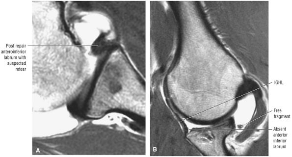 |
|
FIGURE 8.223 ● Retear of the anteroinferior labrum, difficult to appreciate on an axial PD MR arthrogram (A), is easily identified on the corresponding abduction external rotation (ABER) sequence (B).
|
-
The Bankart lesion
-
Anterior labroligamentous periosteal sleeve avulsion (ALPSA)
-
HAGL
-
Capsular laxity
-
Bioabsorbable tacks
-
Transglenoid sutures
-
Suture anchors (used for both soft tissue and osseous Bankart repair)204
capsular laxity, has been associated with high failure rates and tissue necrosis. AMBRI (MDI) patients undergo rehabilitation for at least 3 to 6 months after repair.
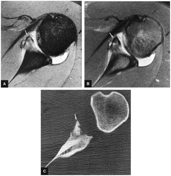 |
|
FIGURE 8.224 ● Chronic Bankart lesion (arrow) in an injured football player is seen on T2* (A), FS PD FSE (B), and axial CT (C) images. On the FS PD FSE image there is a lack of bone marrow edema at the fracture site or in adjacent glenoid subchondral bone marrow. Sclerotic changes are seen in the anterior inferior glenoid rim on the corresponding CT scan (C).
|
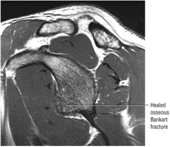 |
|
FIGURE 8.225 ● Sagittal PD FSE image showing a chronic healed osseous Bankart lesion with prominent convex anterior inferior glenoid rim contour (the “beer gut sign”).
|
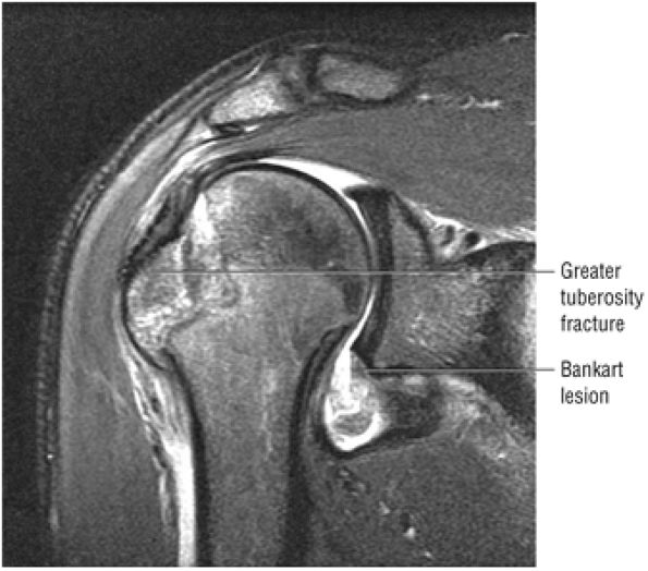 |
|
FIGURE 8.226 ● Coronal FS PD FSE image of a greater tuberosity fracture and a Bankart lesion. The association of a greater tuberosity fracture is more common in patients over 30 years of age.
|
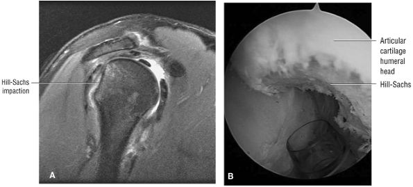 |
|
FIGURE 8.227 ● (A) Posterolateral Hill-Sachs deformity with flattening of the posterior humeral head contour on a sagittal FS PD FSE image. (B) Arthroscopic view of Hill-Sachs fracture.
|
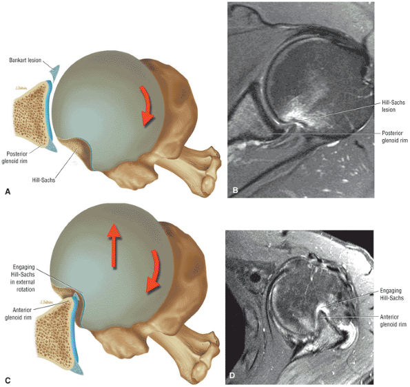 |
|
FIGURE 8.228 ● Stages of engaging Hill-Sachs lesion with posterolateral humeral head defect contacting the posterior glenoid rim (A, B) and subsequently engaging the anterior rim (C, D). The engaging Hill-Sachs reproduces the anterior inferior instability event with humeral head displacement. (A, C) Superior axial views illustrating stages of engagement. (B, D) Axial PD FSE images in external rotation.
|
-
Infection
-
Recurrent instability
-
Loss of external rotation
-
Neurovascular injury
-
Hardware migration
narrower than the superior glenoid. The inverted-pear glenoid has less shearing resistance and decreased resistance to humeral axial forces. The effective glenoid available for humeral rotation is therefore shortened secondary to loss of bone.
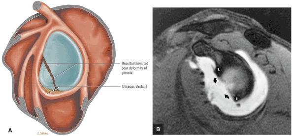 |
|
FIGURE 8.229 ● (A) Sagittal color illustration and (B) sagittal FS T1-weighted MR arthrogram illustrate an inverted-pear deformity with loss of the anterior inferior glenoid rim bone stock in an osseous Bankart lesion. L, labrum; curved arrows, deficient anteroinferior glenoid rim.
|
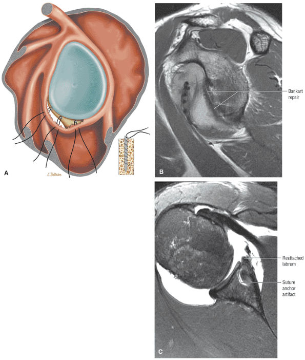 |
|
FIGURE 8.230 ● (A) Illustration of a Bankart repair with anterior inferior suture anchors shown. Anterior capsule and posterior-inferior capsule plication are further techniques used to improve surgical success for anterior-inferior reconstructions. The goal is to restore anterior and posterior capsular integrity and rebuild the anterior labral wedge. Associated SLAP lesions and middle glenohumeral ligament detachments are also repaired. The reattached anterior inferior labrum is seen from the equator to the inferior pole of the glenoid on sagittal FS PD FSE image (B) and axial FS PD FSE image (C).
|
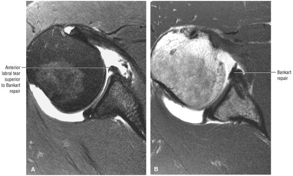 |
|
FIGURE 8.231 ● Axial FS PD FSE MR arthrogram (A) shows labral detachment superior to the Bankart repair shown in (B), a PD FSE MR arthrogram.
|
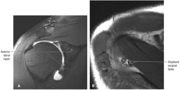 |
|
FIGURE 8.232 ● (A) Coronal FS PD FSE and (B) axial T2 FSE images show displaced tacks located posterior to the supraspinatus muscle after extensive Bankart repair. These dislodged tacks may lead to degenerative glenohumeral arthrosis and synovitis. The axillary recess, subscapularis, and bursa are common locations.
|
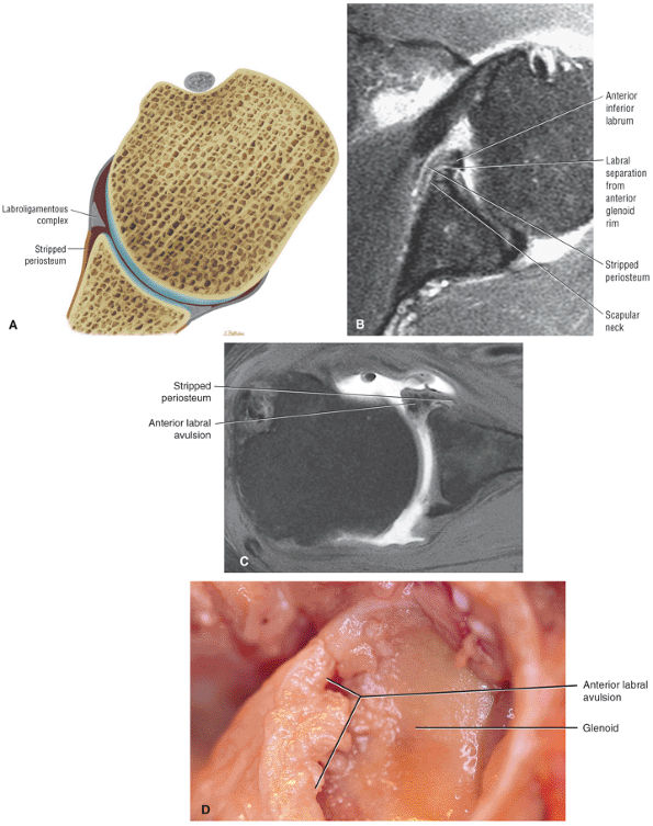 |
|
FIGURE 8.233 ● (A) Axial color graphic, (B) axial FS PD FSE image, (C) axial T1 MR arthrogram (in a separate case), and (D) corresponding gross dissection in Perthes lesion, a labral ligamentous avulsion with intact but medially stripped periosteum along the anterior glenoid neck.
|
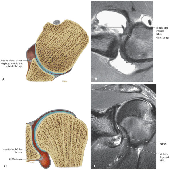 |
|
FIGURE 8.234 ● (A) ALPSA axial (transverse plane) color illustration, (B) axial FS PD FSE image, (C) coronal color illustration, and (D) coronal FS PD FSE image of an ALPSA lesion (anterior labroligamentous periosteal sleeve avulsion) with medial and inferior rotation of the anteroinferior labroligamentous complex. The ALPSA is also referred to as a medialized Bankart lesion.
|
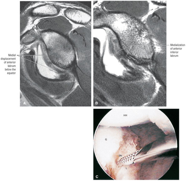 |
|
FIGURE 8.235 ● (A, B) Sagittal PD FSE MR arthrograms demonstrate progressive (B is medial to A) medialization of the displaced and rotated inferior glenohumeral ligament labral complex. (C) Corresponding arthroscopic view of a displaced ALPSA lesion. The labrum and fibrous tissue may resynovialize anterior to the neck of the glenoid.
|
-
Failure at the anatomic neck of the humerus causes HAGL and bony HAGL lesions.
-
Failure at both the humerus and glenoid causes AIGHL lesions.
-
Posterior capsular detachment and failure of the posterior band attachment to the humerus causes reverse HAGL lesions.
-
Failure of the IGHL glenoid attachment without labral avulsion causes glenoid avulsion of the glenohumeral ligaments (GAGL) lesions.
-
Medial displacement of the IGHL associated with a Bankart causes an inferior ALPSA lesion.
-
Mid-axillary pouch tears
-
Axillary pouch sprain and scarring of the IGHL at the glenoid attachment (partial or healed GAGL)
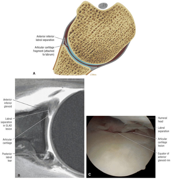 |
|
FIGURE 8.236 ● (A) Axial color section, (B) axial FS PD FSE MR arthrogram, and (C) arthroscopic view of a GLAD (glenolabral articular disruption) or GARD (glenoid articular rim divot) lesion with a flap tear of the anterior inferior labrum and chondral defect of the adjacent articular cartilage.
|
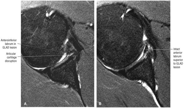 |
|
FIGURE 8.237 ● Axial FS PD FSE images show a GLAD lesion anteroinferiorly (A) with intact anterior labrum directly superiorly (B). There was no associated glenohumeral instability.
|
inferior quadrant of the humeral origin of the IGHL. The goal of arthroscopic HAGL repair is to mobilize and suture the avulsed capsular edge; therefore, HAGL lesions are treated by surgical reattachment of the glenohumeral ligament to its humeral insertion.
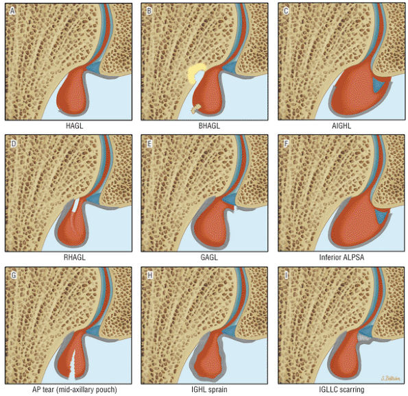 |
|
FIGURE 8.238 ● Capsular IGL lesions illustrated in the coronal plane include: (A) HAGL (humeral avulsion of the glenohumeral ligament), (B) BHAGL (bony humeral avulsion of the glenohumeral ligament), (C) AIGHL (anterior inferior glenohumeral ligament), (D) RHAGL (reverse HAGL), (E) GAGL (glenohumeral avulsion of the glenohumeral ligaments), (F) inferior ALPSA (anterior labroligamentous periosteal sleeve avulsion), (G) mid-axillary pouch (AP) tear, (H) IGHL sprain, (I) IGLLC (inferior glenohumeral ligament labral complex) scarring.
|
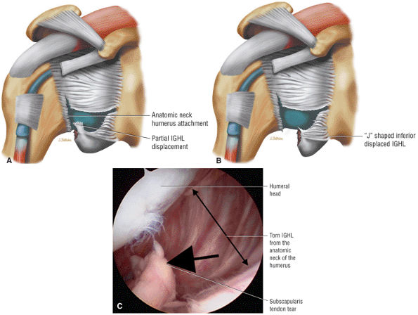 |
|
FIGURE 8.239 ● Stages of a displaced HAGL tear in the anterior atomic neck attachment of the IGHL(IGL). (A) Coronal illustration with partial IGLinferior displacement. (B) Coronal illustration of a J-shaped or inferiorly displaced IGL. (C) Arthroscopic view of a torn subscapularis tendon (short arrow) and humeral avulsion of the IGL (double-headed long arrow) creating the J-shaped axillary pouch.
|
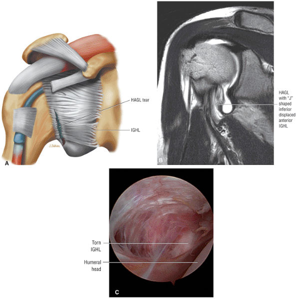 |
|
FIGURE 8.240 ● HAGL lesion on coronal color graphic (A) and coronal T1-weighted MR arthrogram (B). Arthroscopic view (C) demonstrates avulsion of the anterior capsule.
|
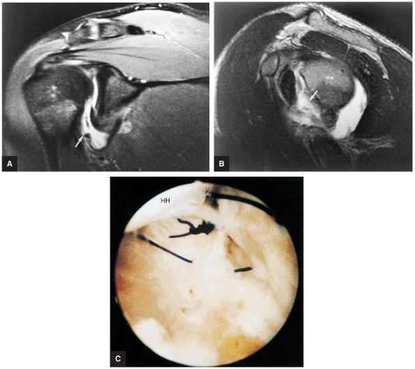 |
|
FIGURE 8.241 ● HAGL lesion wth avulsion of the humeral attachment of the inferior glenohumeral ligament (arrow) on FS PD-weighted FSE coronal oblique (A) and T2-weighted FSE sagittal oblique (B) images. Corresponding arthroscopic photograph (C) shows suturing with coaptation of the detached portion of the IGHL. HH, humeral head.
|
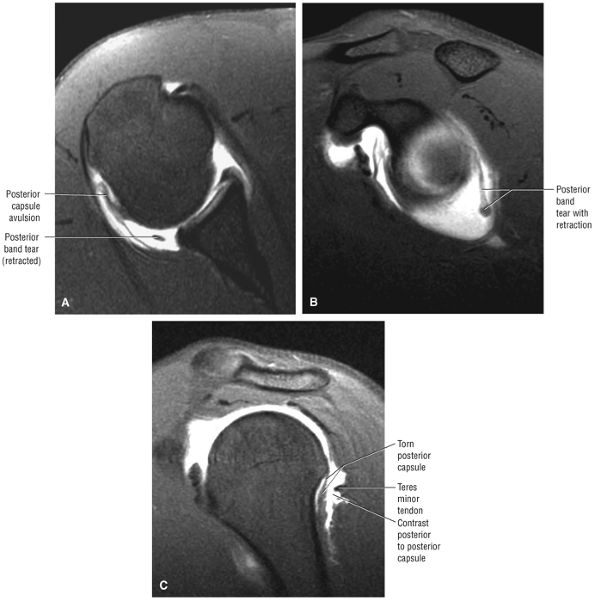 |
|
FIGURE 8.242 ● (A) Axial FS T1 MR arthrogram, (B) sagittal FS T1MR arthrogram, and (C) sagittal FS T1-weighted image showing reverse humeral avulsion of the glenohumeral ligaments (RHAGL) associated with both posterior capsular avulsion and rupture of the posterior band of the IGL. There is extension of contrast between the torn posterior capsule and teres minor.
|
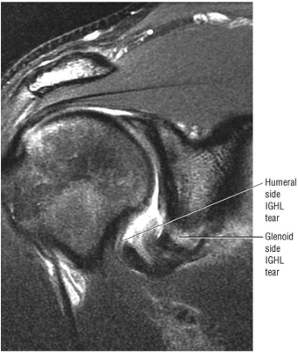 |
|
FIGURE 8.243 ● Coronal FS PD FSE image of floation anterior inferior glenohumeral ligament (AIGL) with unattached glenoid (Bankart) and humeral (HAGL) components.
|
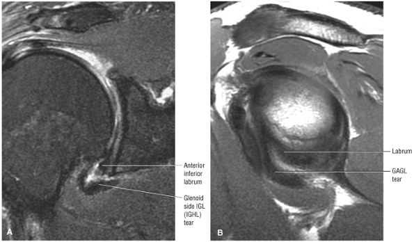 |
|
FIGURE 8.244 ● (A) Coronal FSPD FSE and (B) sagittal PD FSE images show glenoid avulsion of the glenohumeral (GAGL) with intact anterior inferior labrum.
|
IGHL from the inferior pole of the glenoid without associated disruption of the inferior labrum. The Bankart lesion is more common at the location of the inferior pole with involvement of both the anteroinferior labrum and medial capsular displacement.
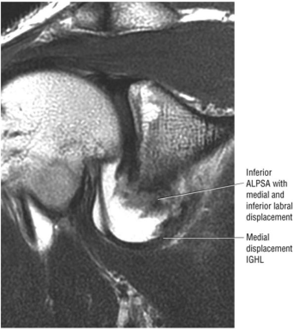 |
|
FIGURE 8.245 ● Coronal T1-weighted MR arthrogram of inferior ALPSA with medial displacement of both the anterior inferior labrum and IGHL (IGL) underneath the inferior pole of the glenoid and along the inferior neck.
|
-
The reverse Hill-Sachs and the reverse Bankart lesions are associated with posterior instability.
-
The reverse HAGL lesion is characterized by tearing of the posterior capsule at the humeral attachment.
-
Posterosuperior labral tears may occur as part of posterior SLAP 2 or posterior peel-back lesions.
-
The Bennett lesion occurs in the throwing athlete and is visualized as an extra-articular posterior ossification.
instability may also occur as an operative complication in patients with MDI after a misdirected anterior capsular procedure. With arthroscopy it is possible to assess associated intra-articular lesions, including labral tears, avulsions, and articular surface rotator cuff, SLAP, and biceps lesions.215
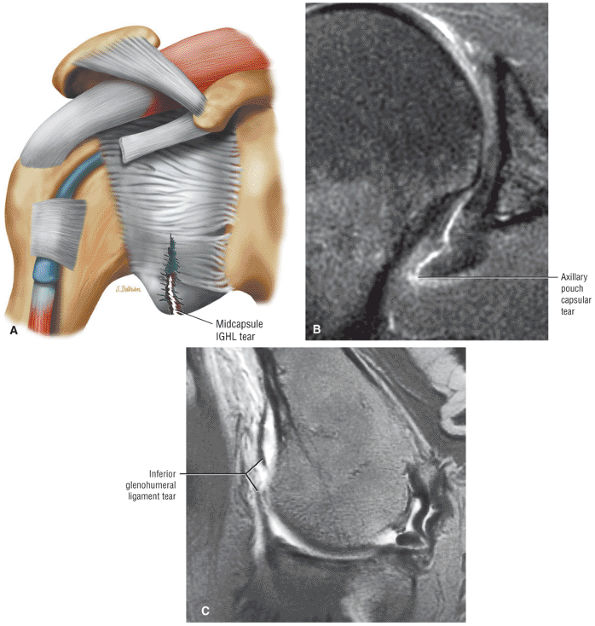 |
|
FIGURE 8.246 ● Mid-axillary pouch tear of the IGHL (IGL) on a coronal color graphic centered on the axillary pouch (A) and a coronal FS PD FSE image (B). (C) Abduction external rotation (ABER) T1-weighted MR arthrogram in a separate case. (From
Stoller DW. MRI, arthroscopy, and surgical anatomy of the joints. Philadelphia: Lippincott-Raven, 1999.
) |
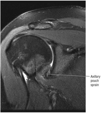 |
|
FIGURE 8.247 ● Coronal FS PD FSE image of axillary pouch hyperintensity after traumatic injury with abduction and external rotation component.
|
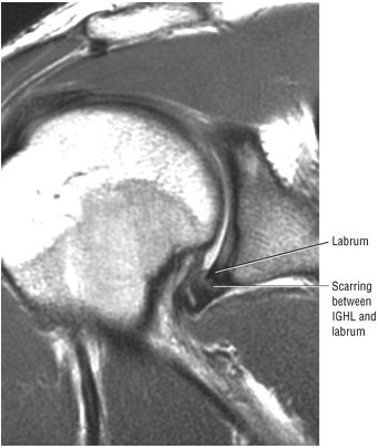 |
|
FIGURE 8.248 ● Intermediate-signal-intensity scarring of the IGL attachment to the inferior labrum and inferior pole of the glenoid without labral disruption on a coronal PD FSE image.
|
-
A reverse Hill-Sachs lesion (notch sign or trough lesion) in the anteromedial humeral head (Fig. 8.250)
-
Fractures of the posterior glenoid margin (reverse osseous Bankart lesion) associated with a posterior labral tear (Fig. 8.251)
-
Deficiency of the posterior glenoid rim (see Fig. 8.251)218
-
Fractures of the lesser tuberosity associated with a posterior dislocation secondary to the pull of the supra-scapularis tendon insertion with or without tears of the subscapularis tendon and teres minor tendon
-
Fracture of the acromion/distal clavicle (Fig. 8.252)
-
A posterior labrocapsular periosteal sleeve avulsion (POLPSA) (Fig. 8.253).217 Normally the posterior capsule attaches directly to the posterior aspect of the posterior labrum. The posterior labrum is secured to the glenoid by the posterior scapular periosteum. Stripping of the posterior labrum produces the POLPSA lesion.
-
A posterior capsular tear (Fig. 8.254) with an intact posterior labrum (the opposite or reverse of the GAGL lesion of the anterior inferior glenoid)
-
Reverse HAGL with or without associated posterior labral tear (Fig. 8.255)
-
Posterior superior labral tears as part of a posterior SLAP 2 (posterior peel-back lesion) or posterosuperior to posterior labral tear in association with a paralabral cyst (Fig. 8.256)
-
Posterior labral tears in the throwing athlete at the mid-glenohumeral joint level as a posterior continuation of a posterior peel-back lesion (especially if associated with posterior humeral subluxation and a posterior eccentric glenohumeral wear pattern)
-
Isolated posterior labral tears (less common)
labrum disruption is identified directly on axial or sagittal images. Axial images may display fluid undermining the base of a torn posterior labrum or show abnormal laxity (redundancy) of a torn posterior capsule. In posterior instability, the humeral head is often subluxed posteriorly relative to the glenoid fossa. In addition, MR arthrography demonstrates the posterior extension of contrast or fluid in the plane between the posterior labrum, the capsule, and the infraspinatus muscle. A lax posteroinferior capsule may show preferential distention with contrast on an axial MR arthrogram.219
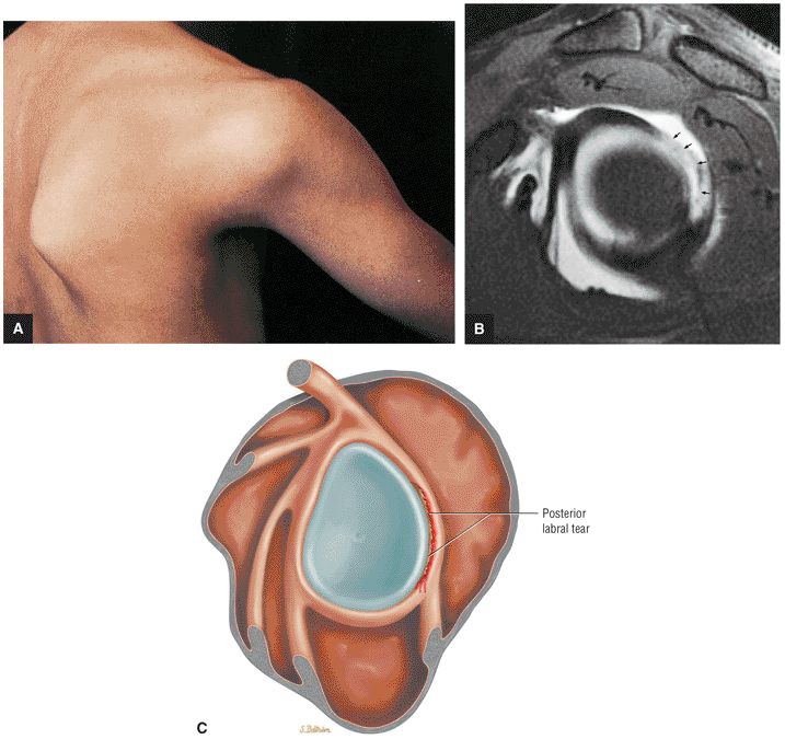 |
|
FIGURE 8.249 ● Posterior instability and labral tear. (A) Posterior instability with anterior rotation of the scapula after dislocation. (B) FS T1-weighted sagittal oblique MR arthrogram with posterior labral avulsion and discontinuity (arrows). (C) Posterior labral tear centered on the posterior quadrant of the glenoid fossa.
|
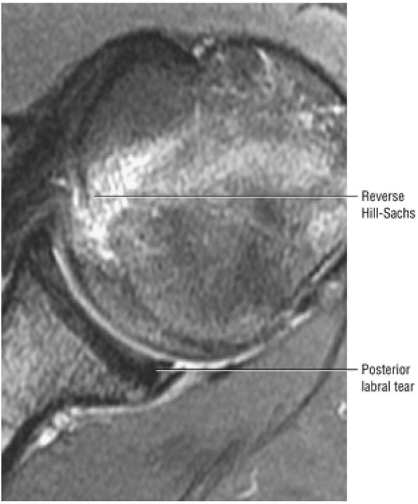 |
|
FIGURE 8.250 ● Reverse Hill-Sachs with hyperintense marrow edema and associated posterior labral tear (reverse Bankart) on an axial FS PD FSE image. Traumatic posterior instability is less common than anterior instability and is more frequently seen with multidirectional instability or as a component of a complex laxity pattern associated with anterior dislocation.
|
-
Referred to as either MDI (multidirectional instability) or AMBRI (atraumatic multidirectional instability, bilateral treated with rehabilitation or inferior capsular shift)
-
MDI must include a component of inferior instability (anteroinferior or posteroinferior).
-
MR findings in MDI may include subtle anterior and posterior glenoid rim sclerosis or static humeral head subluxation in the axial plane.
-
A pancapsular plication is used to selectively tighten lax ligaments.
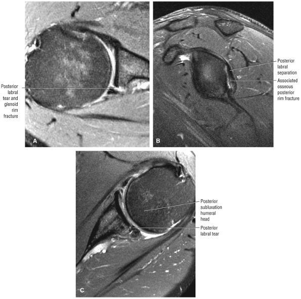 |
|
FIGURE 8.251 ● (A) Axial FS PD FSE and (B) sagittal FSE PD FSE images of posterior labral tear with associated glenoid rim fracture. This represents a reverse bony Bankart lesion. (C) Axial FS PD FSE image shows increased glenoid version associated with a posterior labral tear and mild posterior subluxation. Patients with posterior instability frequently have pain exacerbated by activities that posteriorly load the glenohumeral joint in shoulder adduction.
|
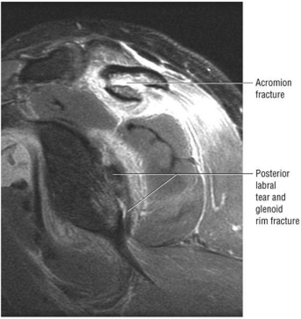 |
|
FIGURE 8.252 ● Sagittal FS PD FSE image shows an acromion fracture associated with a posterior shoulder dislocation. The posterior dislocation findings may be overlooked on conventional radiographs.
|
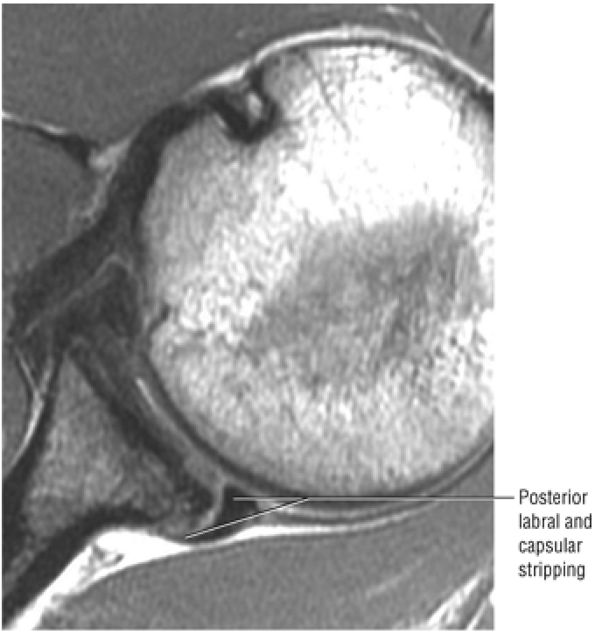 |
|
FIGURE 8.253 ● Axial PD FSE image of a posterior labrocapsular periosteal sleeve avulsion (POLPSA) with stripping of the posterior labrum and capsule with separation from the posterior glenoid rim.
|
-
Selective tightening of lax ligaments
-
Widening of the surface area of the labrum and thus the weight-bearing capacity of the glenoid
-
Augmentation of the “chock block” effect of the labrum by deepening the relative concavity of the glenoid fossa
-
Closing of the rotator interval, providing a temporary internal splint (the SGHL and MGHL do not heal together) by reducing forces on the inferior capsule and limiting external rotation and inferior subluxation in the early postoperative period
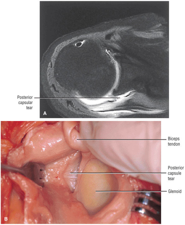 |
|
FIGURE 8.254 ● (A) Posterior capsular tear with firmly attached posterior labrum shown on an axial FS T1-weighted MR arthrogram. (B) Corresponding surgical exposure of torn posterior capsule. (From
Stoller DW. MRI, arthroscopy, and surgical anatomy of the joints. Philadelphia: Lippincott-Raven, 1999
, with permission.) |
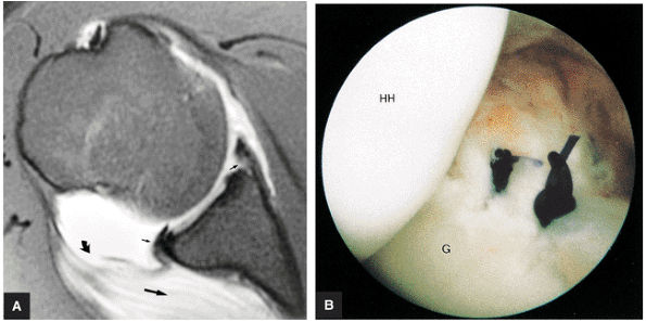 |
|
FIGURE 8.255 ● (A) FS T1-weighted MR arthrogram of reverse humeral head avulsion of the glenohumeral ligaments (RHAGL). There is discontinuity of the humeral attachment of the posterior capsule (curved arrow) with extravasation (large straight arrow) of contrast and associated tears of the anterior (Perthes) and posterior labrum (small arrow). Repair of both the posterior labrum and RHAGL is required. (B) Arthroscopic view of posterior labral repair. The RHAGL repair uses two or three anchors and several side-to-side sutures for closure of the capsular flap and reattachment of the capsule to the humeral head.
|
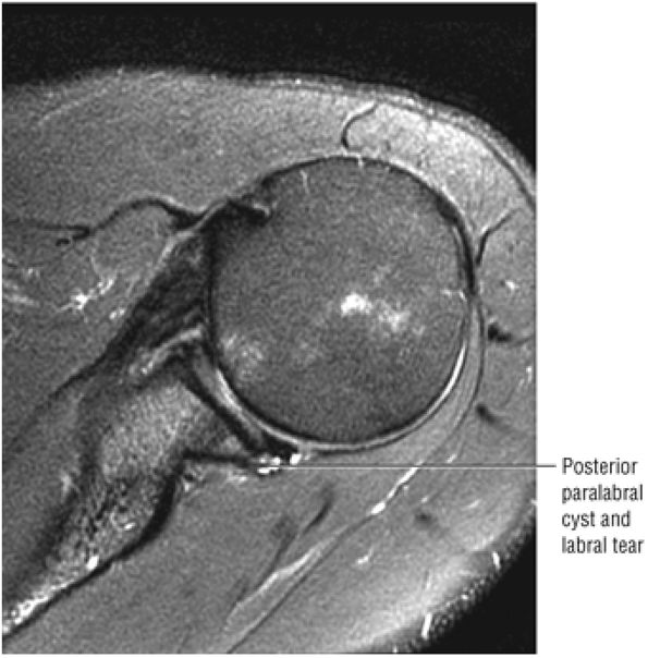 |
|
FIGURE 8.256 ● Axial FS PD FSE image showing association of a posterior labral tear with a paralabral cyst. These posterior para-labral cysts should also be evaluated on sagittal images since they may be extensive and reach from the BLC to the inferior glenohumeral ligament labral complex.
|
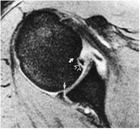 |
|
FIGURE 8.257 ● A reverse Bankart lesion with anteromedial humeral head impaction (curved arrow), anterior labral avulsion, and posterior labral tear. Note fluid undermining the posterior labrum (straight arrow) and anterior fracture fragment (open arrow). The anteromedial defect creates the notch sign or trough lesion.
|
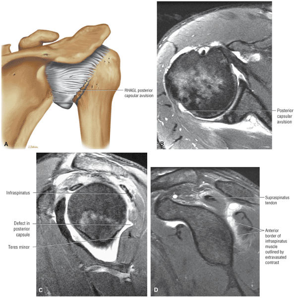 |
|
FIGURE 8.258 ● (A) Posterior coronal color view of RHAGL with avulsion of the posterior humeral attachment of the shoulder capsule. (B) Axial FS PD FSE image shows posterior humeral detachment of the posterior capsule associated with capsular laxity or a wavy contour. (C) A characteristic dimple or defect in the posterior capsule between the infraspinatus and teres minor on a sagittal FS PD FSE image. (D) Direct extension of fluid outlining the anterior muscle of the infraspinatus secondary to posterior capsular rupture can be seen on this sagittal FS PD FSE image.
|
 |
|
FIGURE 8.259 ● (A) Extra-articular ossification of a Bennett lesion on posterior coronal view (color illustration). The Bennett lesion is associated with injury to the posterior superior labrum in the throwing athlete. (B) Axial T2*-weighted GRE image with linear crescentic ossification corresponding to the course of the posterior capsule. This ossification is usually in contact with the posterior glenoid neck. (C) Corresponding sagittal FS PD FSE image with hypertrophic buildup or ossification along the posterior rim. The Bennett lesion usually occurs in the location of greatest posterior glenoid rim wear or sclerosis and inferior to the posterosuperior peel-back lesion.
|
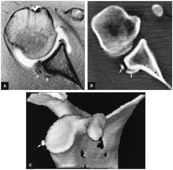 |
|
FIGURE 8.260 ● Bennett lesion with posterior extra-articular ossification (straight arrows) on FS T1-weighted axial arthrographic image (A), axial CT (B), and 3D CT rendering (C).
|
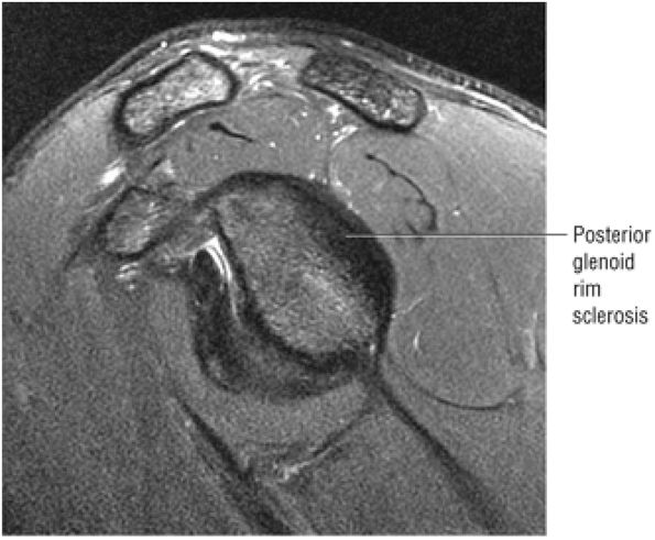 |
|
FIGURE 8.261 ● Posterior glenoid rim sclerosis can be seen on this sagittal FS PD FSE image prior to the development of a posterior peel-back labral tear or Bennett's ossification. This pitcher has a fastball velocity of over 100 mph.
|
-
The sublabral foramen is located in the anterosuperior quadrant of the glenoid fossa. The biceps labral sulcus is identified at the level of the superior pole of the glenoid in the 12-o—clock position.
-
The MGL may be cord-like, thin, or absent.
-
When cord-like, the MGL presents as an isolated variation or in conjunction with a prominent anterior band of the IGL or as part of the Buford complex.
-
Since there is no anterosuperior labrum in the Buford complex, a sublabral foramen cannot exist. In the presence of a prominent anterior band of the IGHL and a Buford complex, the anterior band may form an apparent or pseudo-sublabral foramen above the equator.
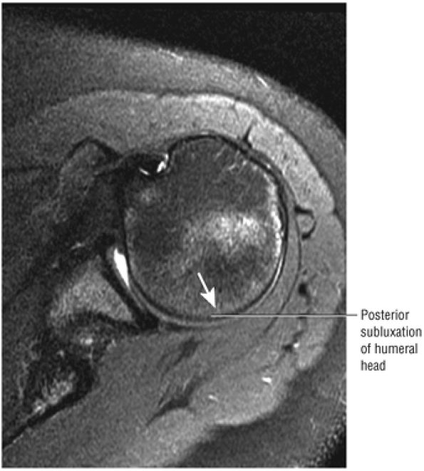 |
|
FIGURE 8.262 ● Axial FS PD FSE image of posterior subluxation of the humeral head in a 20-year-old swimmer with a clinical “loose” shoulder. An episode of trauma may aggravate a shoulder with a preexisting or mild underlying laxity.
|
ant in 17% of specimens.55 Care must be taken not to mistake a sublabral foramen, which can vary in size from a few millimeters up to the entire anterosuperior quadrant above the level of the subscapularis tendon,61 for a SLAP lesion or a Bankart lesion. Hyperintense fluid, which undermines the anterosuperior labrum, may be over-read as a SLAP lesion. In contrast to a Bankart lesion, the sublabral foramen is seen superior to the anterior glenoid notch or above the physeal line representing the superior one third of the glenoid. The Bankart lesion usually involves a labral tear or avulsion at or below the level of the subscapularis tendon on axial MR images. This is below the physeal line or equator. (The physeal line divides the bony glenoid into an upper one third and lower two thirds, corresponding to the two glenoid ossification centers. It is also referred to as the equator, as identified at the region of the anterior glenoid notch.61) Direct communication between the sublabral foramen and the subscapularis bursa can be seen on MR arthrography. A sublabral foramen may be seen with a type 2 or type 3 BLC. The sublabral foramen is anterior to the biceps labral sulcus when viewed in the coronal plane (Fig. 8.266).
near the glenoid rim (Fig. 8.267).57,61 In 19% of cases, the MGHL has a cord-like morphology, compared with the more normal sheet-like appearance of ligamentous tissue (Fig. 8.268). An attenuated or thin variation of the MGHL is observed in 5% of shoulders. Complete absence of the MGHL may be associated with a congenitally lax anterior capsule.
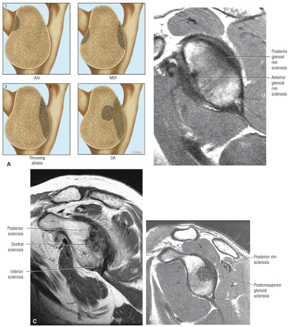 |
|
FIGURE 8.263 ● Four types of glenoid fossa sclerosis. (A 1, upper left) Anterosuperior impingement (ASI) pattern. (A 2, upper right) Multidirectional instability (MDI). (A 3, lower left) Posterior glenoid rim wear in the throwing athlete. (A 4, lower right) Osteoarthritis pattern with central glenoid fossa and posterior glenoid wear. (B) Sagittal FS PD FSE image showing MDI wear with anterior and posterior glenoid rim sclerosis. (C) Osteoarthritis in a 70-year-old patient with posterior wear and central glenoid sclerosis. The initial change of inferior rim sclerosis can also be seen. (D) Similar osteoarthritis pattern in the older elite pitcher with central and posterior rim sclerosis without the degenerative changes of the inferior pole. Central or posterosuperior glenohumeral fossa sclerosis is an unusual finding in the younger throwing athlete; instead, wear is initially limited to the posterior rim.
|
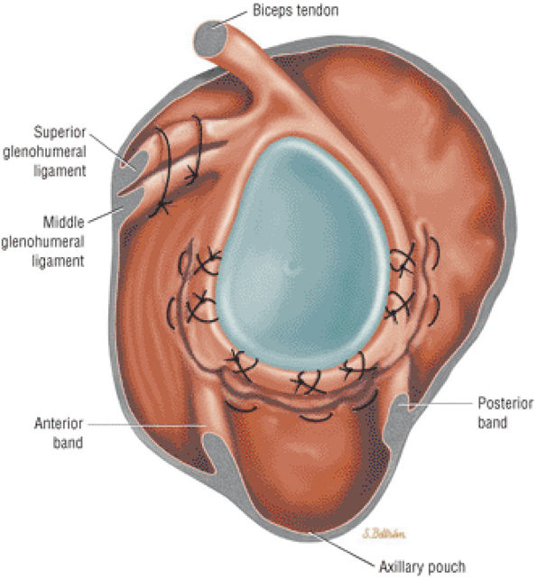 |
|
FIGURE 8.264 ● Arthroscopic pancapsular plication for treatment of multidirectional instability with the IGL and capsule folded to the labrum from the posteroinferior quadrant to the anteroinferior quadrant. The rotator interval is closed, and the final result is to have the humeral head centralized within the glenoid fossa.
|
-
A cord-like MGHL
-
An MGHL that attaches directly to the superior labrum anterior to the biceps (at the base of the biceps anchor)
-
An absent anterosuperior labrum52,58
-
An absent anterior labrum at and above the level of the subscapularis tendon as assessed on axial images. A sublabral foramen can only exist in the presence of an anterior superior labrum.
-
The anterior inferior glenoid labrum below the level of the subscapularis tendon is firmly attached to the glenoid with normal morphology.
-
A cord-like MGHL must be identified anterior to the glenoid rim.
-
There may be remnant or hypoplastic anterosuperior labral tissue identified on axial images at the level of the subscapularis tendon.
anterior labrum on axial images above the equator. Below the equator the prominent anterior band may appear to be adherent to the anteroinferior labrum and is thus indistinguishable. In the presence of a prominent or thickened anterior band, the anterosuperior labrum is either attenuated (hypoplastic) or absent. Demonstration of the course of the anterior band deep to the MGHL on corresponding axial images prevents the misdiagnosis of a labral tear. In this case the anterior band of the IGHL effectively functions as an anterior labrum and attaches superiorly at the BLC. The following variations can exist with a prominent anterior band of the IGHL:
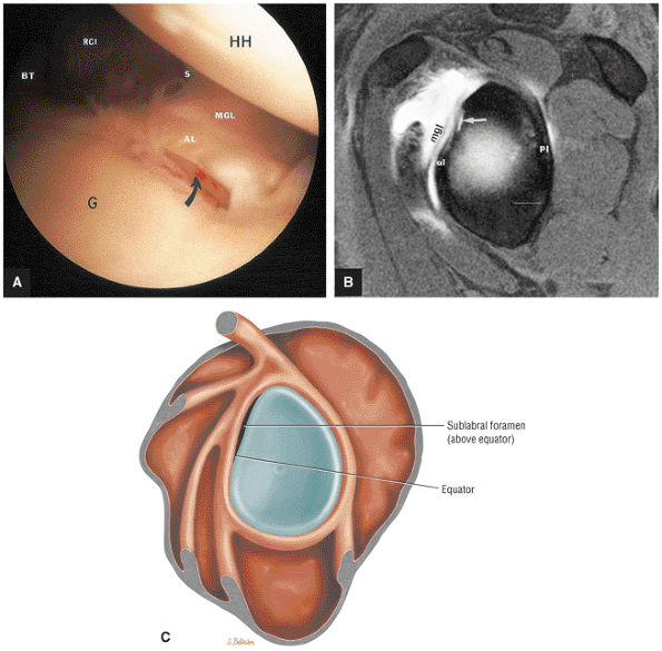 |
|
FIGURE 8.265 ● (A) An arthroscopic photograph of a normal anatomic variant of the sublabral foramen with a missing anterior labrum attachment above the epiphyseal line of the glenoid (curved arrow). AL, anterior labrum; BT, biceps tendon; G, glenoid; HH, hum-eral head; MGL, middle glenohumeral ligament; RCI, rotator cuff interval or Weitbrecht's foramen; S, subscapularis tendon. (B) Sublabral foramen (arrow) shown above the equator (above the anterior glenoid notch) on an FS T1-weighted sagittal oblique MR arthrogram. Contrast extends between the anterosuperior labrum and the glenoid rim as a normal variant. MGL, middle glenohumeral ligament; al, anterior labrum; pl, posterior labrum. (C) Lateral view color graphic of a sublabral foramen beneath the anterior superior labrum.
|
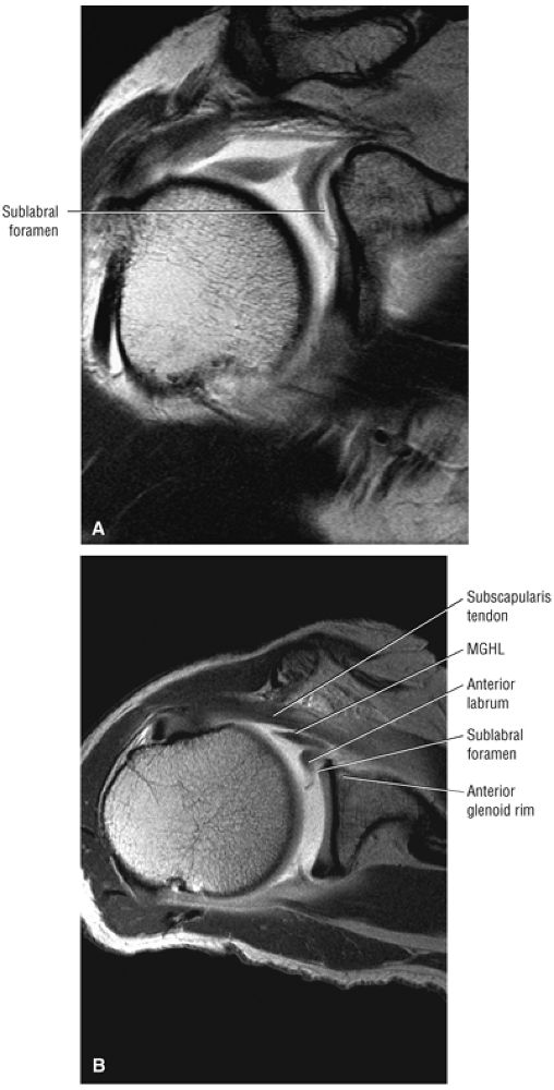 |
|
FIGURE 8.266 ● The sublabral foramen is present in 14% of shoulders and can range in size from a few millimeters to the entire anterosuperior quadrant between the superior pole and the equator. The sublabral foramen should not be mistaken for a Bankart labral detachment or a SLAP lesion of the biceps labral complex. The sublabral foramen is often associated with a cord-like middle glenohumeral ligament. This assumes that the cord-like MGL is not associated with a Buford complex, since a sublabral foramen cannot exist in this variation (because the anterosuperior labrum is absent). (A) Coronal T1 MR arthrogram with a large anterosuperior sublabral foramen. (B) Corresponding axial T1 MR arthrogram demonstrating the subscapularis, the middle glenohumeral ligament (MGHL), the anterior labrum, the sublabral foramen, and the anterior glenoid as visualized from anterior to posterior.
|
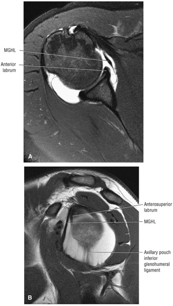 |
|
FIGURE 8.267 ● Normal middle glenohumeral ligament (MGHL or MGL) on axial FS PD FSE (A) and sagittal FSE (B) images. The MGL is the most variable in morphology of all the anterior glenohumeral capsular ligaments. In the most common appearance (70% of cases) the MGL represents a folded anterior capsular thickening that crosses the subscapularis tendon at a 45° angle. The MGL inserts onto the anterosuperior glenoid neck at the level of or just medial to the labrum. The MGL, superior glenohumeral ligament, and anterosuperior labrum thus converge at the anterior superior pole of the glenoid. This ligament configuration creates one opening into the subscapularis recess anterior to the leading edge of the MGL.
|
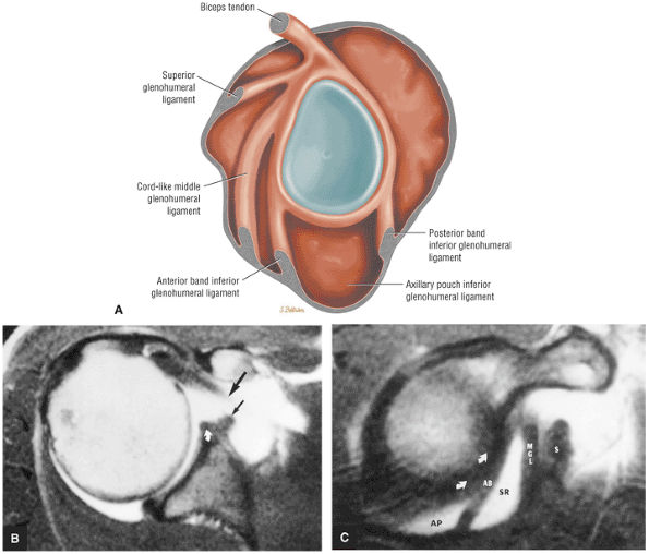 |
|
FIGURE 8.268 ● The cord-like middle glenohumeral ligament (MGL) represents the most common variation of MGL anatomy and is seen in up to 20% of normal shoulders. The cord-like MGL has a smooth rope-like or round cross-section instead of the more linear sheet-like morphology. The cord-like MGL attaches either to the neck of the glenoid superiorly or directly to the anterosuperior labrum. The cord-like MGL may be associated with a sublabral pole in cases where it attaches directly to the anterosuperior labrum. This variation does not represent a labral detachment or Buford complex. (A) Lateral color illustration of the cord-like MGL. (B) Enhanced T1-weighted axial images showing a cord-like or hypertrophied MGL (small black arrows) that simulates an avulsion of the anterior labrum. (C) A corresponding enhanced T1-weighted sagittal image displays a normal anterior labrum (curved arrows) and anterior band of the IGL (AB). A thick, cord-like MGL and subscapularis tendon (S) can also be identified. Intra-articular gadolinium contrast is shown in the axillary pouch (AP) of the inferior glenohumeral ligament and in a synovial recess (SR) below the MGL.
|
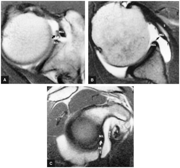 |
|
FIGURE 8.269 ● Cord-like middle glenohumeral ligament (MGL) on T1-weighted enhanced axial images at the level of the coracoid (A) and inferior to the coracoid at the level of the subscapularis tendon (B). Curved arrow, filamentous attachment to cord-like MGL; large straight arrow, cord-like portion of MGL; small straight arrows, thin portion of MGL; AGL, anterior glenoid labrum. (C) Corresponding T1-weighted enhanced sagittal oblique image showing the relationship of the MGL to the anterior band of the IGL (AB; straight arrow), the anterior glenoid labrum (AGL; curved arrow), the middle glenohumeral ligament (MGL), and the subscapularis tendon (S). The MGL is located in the plane between the subscapularis tendon and the anterior band of the IGL or anterior glenoid labrum.
|
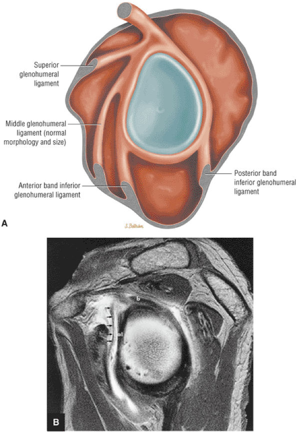 |
|
FIGURE 8.270 ● (A) Normal MGL morphology on lateral glenoid exposure. (B) Sagittal T1-weighted MR arthrogram demonstrating a thin (with no area of thickening) linear MGL (arrows) anterior to the anterior labrum (al). In 10% of shoulders the MGL is a thin attenuated structure or completely absent. The anterior band of the IGL may be inversely prominent in association with an attenuated or fibrous MGL variation. b, biceps; al, anterior labrum.
|
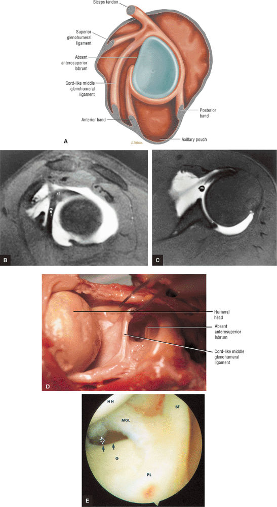 |
|
FIGURE 8.271 ● (A) Lateral color illustration of a Buford complex with cord-like MGL attached to superior labrum just anterior to the base of the biceps anchor, and absent anterosuperior labrum above the equator. (B) Thick cord-like middle glenohumeral ligament (mgl) attaching directly to the superior labrum (sl) on an FS T1-weighted sagittal oblique arthrogram. (C) Corresponding FS T1 axial image displays the cord-like middle glenohumeral ligament (m) with an absent anterior superior labrum as a normal variant. Note that the posterior labrum (p) is present. (D) Corresponding gross specimen demonstrates the cord-like MGL, which attaches directly to the superior labrum. (E) An arthroscopic view of cord-like MGL in a Buford complex. The anterior superior glenoid edge (black arrows) shows an absence of the labrum as a normal variant in association with prominent MGL. The MGL originates from the anteromedial humeral neck and attaches medially on the glenoid (G) and the neck of the scapula. Open arrow, subscapularis recess; BT, biceps tendon; HH, humeral head; PL, posterior labrum.
|
-
Prominent anterior band plus a small anterosuperior labrum (Fig. 8.272)
-
Prominent anterior band plus an absent anterosuperior labrum (Fig. 8.273)
-
Prominent anterior band plus a cord-like MGHL (Fig. 8.274) (associated with an absent or small anterosuperior labrum)
-
The superior labrum
-
The anterosuperior (superior to the mid-glenoid notch) labrum
-
The anteroinferior labrum
-
The inferior labrum
-
The posteroinferior labrum
-
The posterosuperior labrum
-
Degenerative lesions
-
Flap tears
-
Vertical split nondetached tears
-
Bucket-handle tears
-
SLAP lesions
-
A biceps labral sulcus greater than 5 mm is abnormal.
-
Superior paralabral cysts that often extend into the spino-glenoid notch communicate with SLAP 2 or posterior SLAP 2 (peel-back) lesions.
-
Inferior displacement of the superior labrum (relative to the biceps labral junction) is associated with bucket-handle SLAP morphology.
-
SLAP tears are grouped into 10 subtypes. Four primary types were initially described and six further types were subsequently characterized.
-
The SLAP 2 or classic SLAP lesion is further subdivided into anterior SLAP 2 in the SLAC lesion and posterior SLAP 2 in the posterior peel-back lesion.
-
A SLAP fracture is a posterosuperior medial humeral head chondral fracture in association with a SLAP lesion.
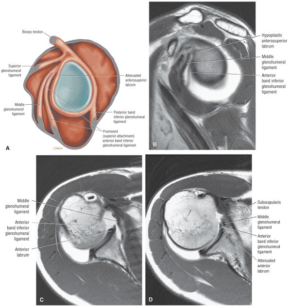 |
|
FIGURE 8.272 ● Prominent or superior (above the equator) attachment of the anterior band of the inferior glenohumeral ligament coursing anterior to a small anterosuperior labrum and attaching at the level of the superior labrum. (A) Lateral color illustration. (B) Sagittal PD-weighted MR arthrogram. (C) Inferior axial PD-weighted MR arthrogram at the inferior edge of subscapularis tendon. (D) Axial PD-weighted MR arthrogram at the level of superior edge of subscapularis tendon above the equator.
|
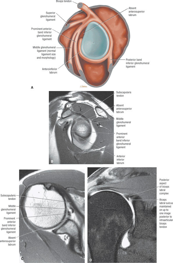 |
|
FIGURE 8.273 ● (A) Prominent anterior band of the IGHL with absent anterosuperior labrum. This is not a Buford complex, since the MGL is not cord-like. (B –D) If the anterosuperior labrum is absent, as in the case of a prominent anterior band, Buford complex, or Buford variant (cord-like MGL plus a prominent anterior band), there may be a normal sulcus between the superior labrum and superior pole of the glenoid. This biceps labral sulcus may be seen one image posterior to the biceps labral junction in association with the Buford complex or prominent anterior band of the IGL. (B) Sagittal T1-weighted MR arthrogram. (C) Axial T1-weighted MR arthrogram. (D) Coronal FS PD FSE MR arthrogram.
|
-
A biceps labral sulcus measurement of less than 5 mm is within a normal range, although the biceps labral sulcus is most commonly less than 3 mm on coronal MR images (see Fig. 8.275). A sulcus of greater than 5 mm is abnormal.227
-
On review of coronal oblique images at or posterior to the osseous anteroinferior pole of the glenoid, there should not be hyperintense signal intensity located between the intra-articular biceps tendon and the superior labrum (Fig. 8.276).
-
There is frequently a normal lateral oblique cleft of fluid signal intensity between the biceps tendon and the superior labrum anterior to the biceps labral junction (Fig. 8.277). A firmly attached connection between the intra-articular biceps and the superior labrum prevents increased signal intensity between the biceps tendon and the superior labrum.
-
A paralabral cyst adjacent to the superior labrum usually communicates with a classic SLAP 2 or the posterior component of a SLAP 2 lesion (see Fig. 8.276).
-
Inferior displacement of the superior labrum separated from its biceps connection is associated with bucket-handle SLAP morphology (Fig. 8.278).
-
Fragmentation or splitting of the superior labrum into separate fragments is associated with bucket-handle SLAP tear patterns. This SLAP tear pattern should not
P.1380P.1381P.1382
be mistaken for the normal biceps labral sulcus.233 Avulsion of the superior labrum from the superior pole of the glenoid will result in an enlarged biceps labral sulcus (Fig. 8.279). -
SLAP tears occur either centrally or eccentrically with the superior labrum at the biceps labral junction. Eccentric tears are located adjacent to either the glenoid (Fig. 8.280) or humerus (Fig. 8.281).
-
SLAP tears are usually parallel to the long axis of the posterosuperior labrum posterior to the biceps tendon (Fig. 8.282).234
-
Superior displacement (Fig. 8.283) of the biceps labral complex relative to the superior pole of the glenoid on sagittal images is associated with SLAP 2 lesions.
-
Common patterns of SLAP tears demonstrate a spectrum of lesions from detachment at the biceps labral junction to splitting and fragmentation of the labrum (Fig. 8.284).
-
A SLAP tear occurs commonly in one of three locations:
-
Between the biceps tendon and the superior labrum
-
Within the superior labrum
-
Between the superior labrum and the superior pole of the glenoid
-
-
Visualization of three distinct hypointense structures (the biceps tendon and the split superior labrum) on sagittal images through the BLC correlates with bucket-handle morphology (Fig. 8.285).
-
Complex or extended SLAP lesions (SLAP 5 through SLAP 10) may be associated with SLAP 2 or SLAP 3 lesions.
-
A biceps labral sulcus may be seen one image posterior to the biceps labral junction in association with the Buford complex or prominent anterior band of the IGHL.
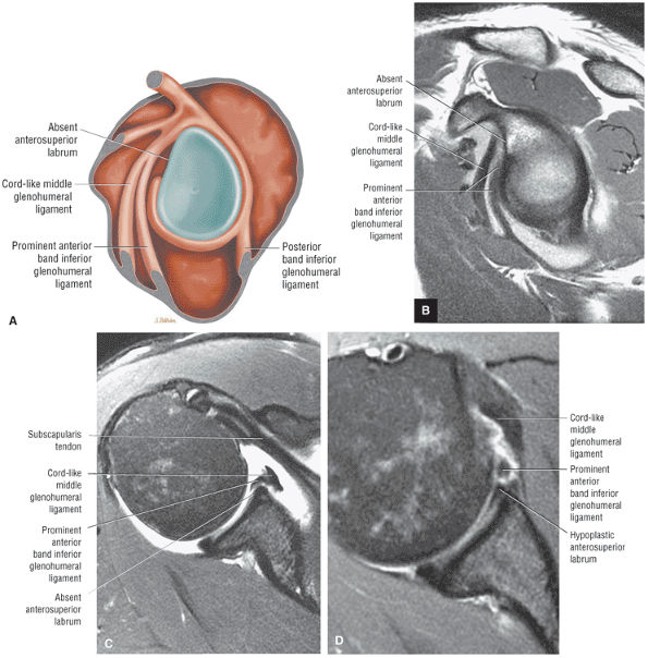 |
|
FIGURE 8.274 ● A prominent anterior band associated with a cord-like MGL and absent anterosuperior labrum on a lateral view color illustration (A), a sagittal PD MR arthrogram (B), and an axial FS PD FSE MR arthrogram (C). Because the MGL is cord-like, this could be considered a Buford variant. The original description of the Buford complex did not include the variant of a prominent anterior band. (D) Axial FS PD FSE image in a separate case demonstrating a combination of a cord-like MGL, a prominent anterior band, and hypoplastic anterior labrum.
|
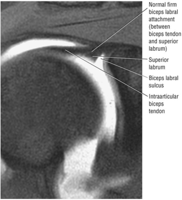 |
|
FIGURE 8.275 ● Coronal FS PD FSE image showing a normal biceps labral sulcus. The medial to lateral measurement is 2.5 mm with the shoulder positioned in neutral to external rotation.
|
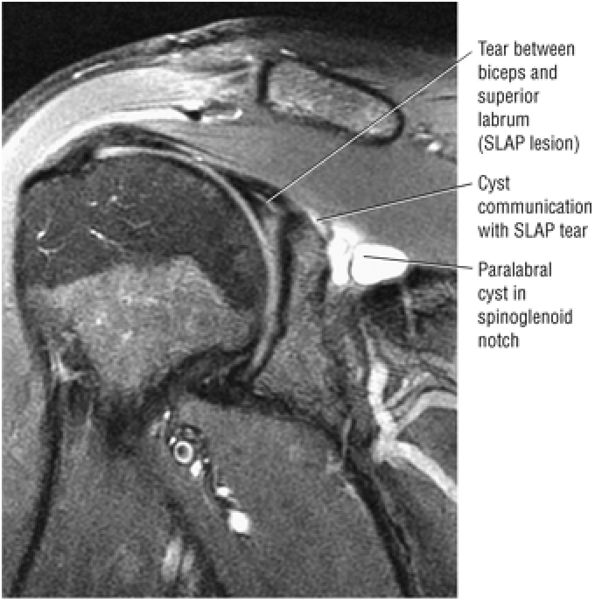 |
|
FIGURE 8.276 ● Linear signal between the intra-articular biceps and superior labrum is abnormal if visualized on a coronal oblique image posterior to an established firm attachment between the superior labrum and biceps tendon. Linear hyperintensity can be seen between the biceps tendon and superior labrum, representing posterior extension of the SLAP tear.
|
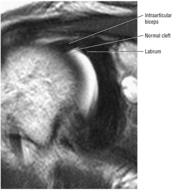 |
|
FIGURE 8.277 ● Coronal PD FSE MR arthrogram displays the normal cleft between the intra-articular biceps and the superior labrum anterior to the 12-o—clock position of the biceps labral complex.
|
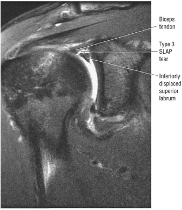 |
|
FIGURE 8.278 ● Coronal FS PD FSE image showing inferior displacement (relative to the biceps anchor) of the superior labrum in a type 3 SLAP lesion with bucket-handle morphology.
|
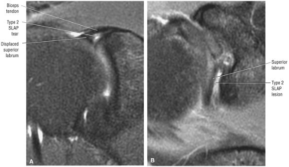 |
|
FIGURE 8.279 ● (A) Coronal FS PD FSE and (B) axial FS PD FSE images show an avulsed superior labrum from the superior pole of the glenoid. The chemical shift artifact of the superior pole articular cartilage may be mistaken for a small labral fragment.
|
-
Type 1 SLAP lesions (Fig. 8.286) are characterized by a frayed and degenerative superior labrum with a normal (stable) biceps tendon anchor.
-
Type 2 SLAP lesions (Fig. 8.287) have similar labral fraying but also have detachment of the superior labrum and biceps anchor, making them unstable. A type 2 lesion may appear similar to the normal free edge of the meniscoid-like superior labrum. In the latter, however, the articular cartilage of the superior glenoid extends to the attachment of the labrum. In a type 2 SLAP lesion there is usually a space or gap between the glenoid articular cartilage and the attachment of the superior labrum and biceps anchor (Fig. 8.288). Displacement of the labrum from the superior glenoid of more than 3 to 4 mm is usually associated with an abnormal superior labrum and biceps anchor attachment. A type 2 SLAP lesion may also be associated
P.1383
with anterior glenohumeral joint dislocation. Tearing of the superior labrum biceps anchor may contribute to anteroinferior capsule and labral stress in the development of anterior instability. The classic SLAP 2 lesion has been subdivided into anterior and posterior SLAP 2 lesions (Fig. 8.289):-
The anterior SLAP 2 lesion (the anterior component of a SLAP 2 lesion) is associated with an anterior supraspinatus articular-side partial cuff tear in the SLAC (superior labrum anterior cuff) lesion (Fig. 8.290).
-
The posterior SLAP 2 lesion (posterosuperior labral tear) is the posterior peel-back lesion in the throwing athlete (Fig. 8.291).
-
-
Type 3 SLAP lesions involve a bucket-handle tear of the superior labrum without extension into the biceps tendon. The biceps anchor is stable and the remaining labrum is intact (Fig. 8.292). Multiple hypointense structures on sagittal images represent the biceps tendon and split superior labrum and are associated with a bucket-handle SLAP tear (Fig. 8.293).236 Type 3 SLAP lesions are commonly associated with anterior labral tears, creating a type 5 SLAP lesion (see below). The inferiorly displaced superior labrum may become entrapped within the superior glenohumeral joint (Fig. 8.294).
-
Type 4 SLAP lesions (Fig. 8.295) also involve a bucket-handle tear of the superior labrum, but in this case with extension into the biceps tendon. A ruptured biceps tendon represents completion of the biceps tendon tear extension, resulting in a proximal biceps stump (Fig. 8.296). A partially torn biceps tendon may displace the superior labral flap into the joint.
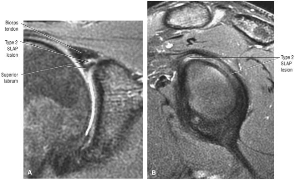 |
|
FIGURE 8.280 ● Eccentric superior labral tear with type 2 SLAP lesion occurring adjacent to the glenoid on (A) a coronal FS PD FSE image and (B) a sagittal FS PD FSE image.
|
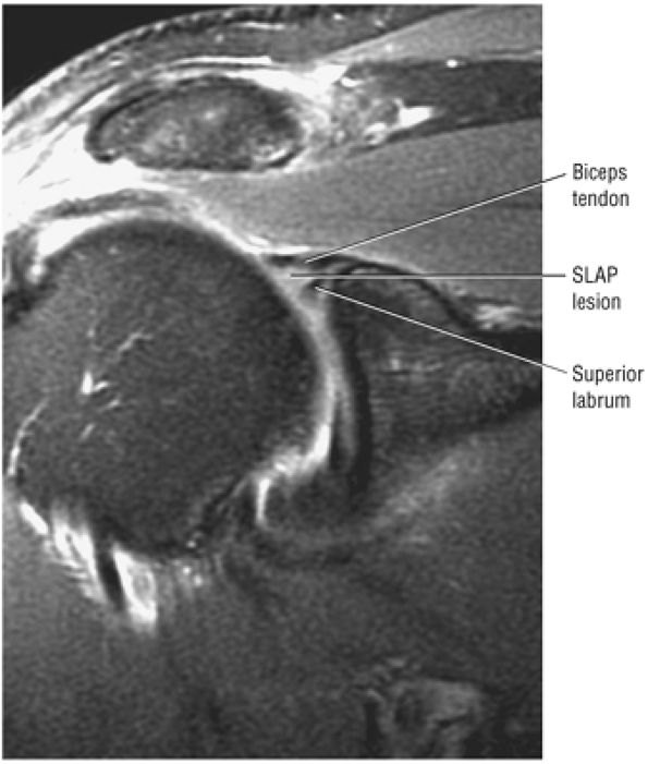 |
|
FIGURE 8.281 ● Eccentric humeral side SLAP tear. If a fragment of the superior labrum is absent or displaced, a type 3 SLAP lesion should be considered. Coronal FS PD FSE image.
|
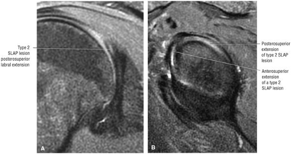 |
|
FIGURE 8.282 ● (A) Coronal FS PD FSE image shows characteristic SLAP 2 linear oblique signal intensity of the posterior superior labrum posterior to the biceps anchor attachment to the superior labrum. (B) Corresponding sagittal FS PD FSE image.
|
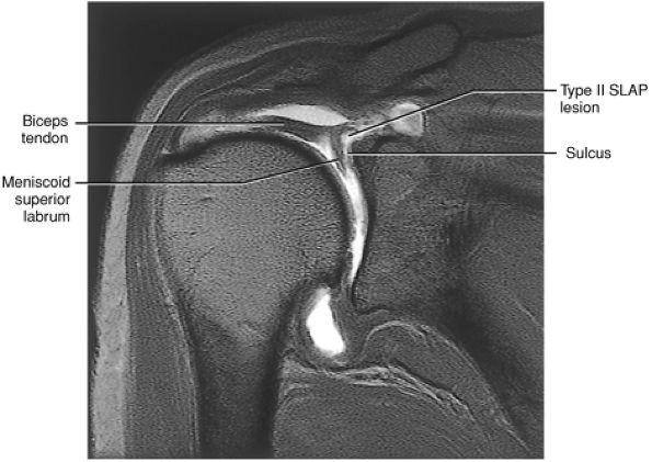 |
|
FIGURE 8.283 ● Coronal T1-weighted MR arthrogram of superior displacement of the biceps anchor and superior labrum (a type 2 SLAP lesion). This may be a difficult MR pattern to distinguish from a normal biceps labral sulcus. Correlation with sagittal images confirms superior displacement of the labrum. (From
Stoller DW. MRI, arthroscopy, and surgical anatomy of the joints. Philadelphia: Lippincott-Raven, 1999
, with permission.) |
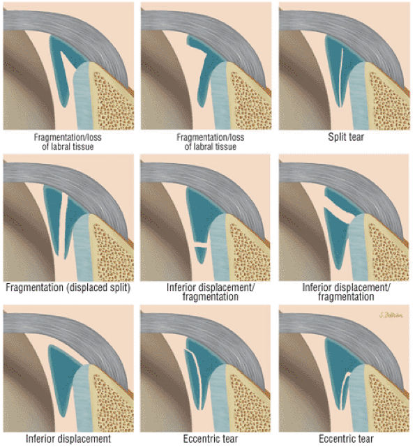 |
|
FIGURE 8.284 ● Common SLAP tear variants include labral fragmentation, vertical split, inferior displacement, and eccentric tears (humeral or glenoid side). A fragmented labrum with gross displacement or absence of labral tissue is associated with bucket-handle morphology. A split of the labrum into separated triangles (double triangle sign) is also associated with a bucket-handle tear pattern. Inferior displacement of the entire superior labrum or a portion of the labrum indicates displacement of a bucket-handle tear. Linear signal without loss of labral tissue or labral displacement/fragmentation is associated with SLAP 2 lesions. There may also be complete superior labral separation from the superior pole with a widened biceps labral sulcus (seen in Fig. 8.279).
|
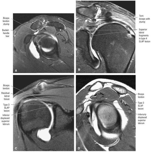 |
|
FIGURE 8.285 ● Type 4 SLAP lesion with the torn biceps stump superior to the two components of the fragmented labrum on (A) a sagittal FS PD FSE image and (B) a coronal FS PD FSE image. In a separate case, a type 3 SLAP bucket-handle tear with an intact biceps tendon and a separate inferiorly displaced labral fragment is visualized on a coronal FS T1-weighted MR arthrogram (C) and a sagittal T1-weighted MR arthrogram (D).
|
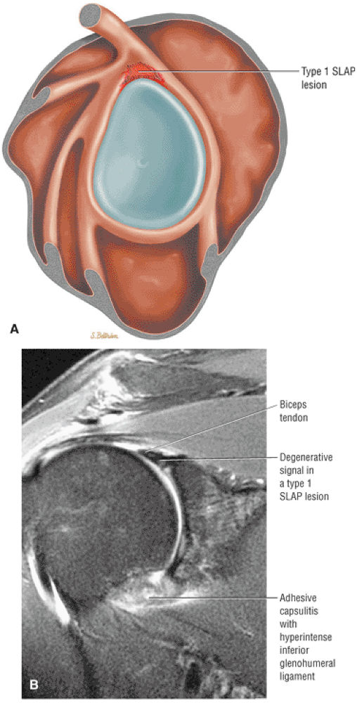 |
|
FIGURE 8.286 ● (A) Lateral color illustration of a type 1 SLAP lesion with fraying of the free edge and intrasubstance degeneration of the superior labrum. This is considered a normal finding in the aging labrum, similar to grade 1 or 2 signal intensity within the degenerative meniscus. This is not considered a symptomatic lesion. (B) Corresponding coronal FS PD FSE image with diffuse intralabral signal intensity without a defined tear, split, fragmentation, or displacement.
|
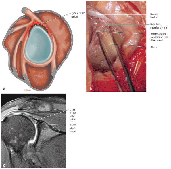 |
|
FIGURE 8.287 ● (A) Type 2 SLAP tear with detached superior labrum and biceps anchor. The labral tear extends from anterior to posterior and may occur within the substance of the labrum or with complete detachment of the biceps and labrum from the superior pole of the glenoid. (B) Type 2 SLAP lesion on a corresponding gross dissection identifying superior labral and biceps tendon detachment. The term “biceps expansion” is more accurate and should be used instead of “torn biceps anchor,” since the origin of the biceps tendon from the supraglenoid tubercle is not involved. The biceps tendon has a separate expansion or attachment directly to the anterior and posterior glenoid labrum. Except for the frayed appearance of the superior labrum, this SLAP lesion could be mistaken for a prominent biceps labral sulcus on coronal oblique MR images. (From
Stoller DW. MRI, arthroscopy, and surgical anatomy of the joints. Philadelphia: Lippincott-Raven, 1999
, with permission.) (C) Coronal FS PD FSE image of a type 2 SLAP lesion defined by linear hyperintensity extending across the superior labrum. The associated biceps labrum sulcus is a normal finding. With an intact coapted triangular outline of the superior labrum, the tear represents a type 2 SLAP and not a bucket-handle tear. |
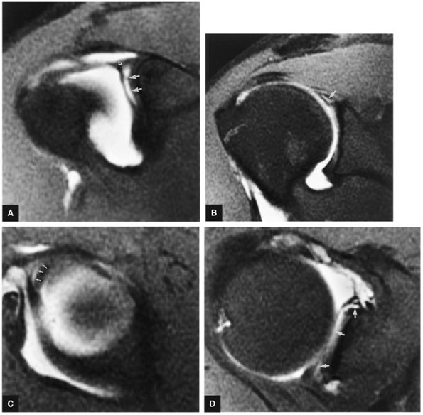 |
|
FIGURE 8.288 ● Type 2 SLAP lesion. (A) Separation of the superior labrum and biceps anchor (b) from the underlying anterior glenoid rim. Hyperintense fluid (arrows) fills the detachment on this FS T1-weighted coronal oblique MR arthrogram. (B) Posterior extension of the tear is shown as a linear hyperintensity through the posterior superior labrum (arrow) on this FS T1-weighted coronal oblique MR arthrogram. Corresponding FS T1-weighted sagittal oblique (C) and axial (D) images display the avulsion (arrows) of the BLC (C) and anterior-to-posterior extension (arrows) of the superior labral tear (D).
|
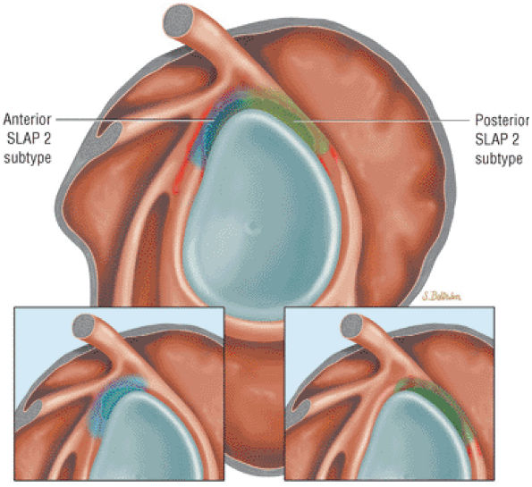 |
|
FIGURE 8.289 ● Location of anterior SLAP 2 (blue) and posterior SLAP 2 (green) subtypes. Hemorrhage is highlighted in red. A classic type 2 SLAP lesion would involve both anterior and posterior components.
|
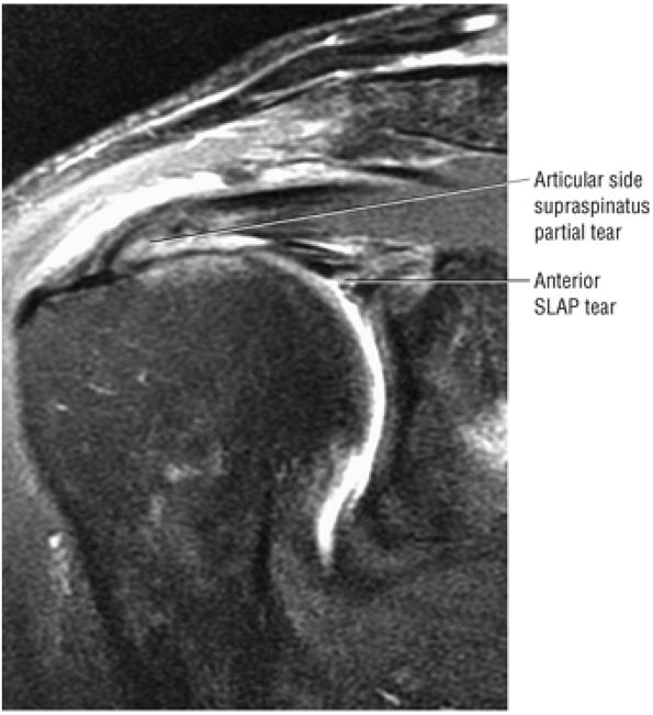 |
|
FIGURE 8.290 ● Coronal FS PD FSE image of an anterior SLAP lesion combined with an articular-side supraspinatus partial tear in a superior labrum anterior cuff (SLAC) lesion.
|
-
Type 5 SLAP lesion (Fig. 8.297) is a SLAP 2 or 3 lesion plus superior extension of a Bankart lesion. A Hill-Sachs posterolateral humeral head fracture and inferiorly displaced superior labrum may be seen on superior axial images through the glenohumeral joint (Fig. 8.298).
-
Type 6 SLAP lesions (Figs. 8.299 and 8.300) are flap tears of the superior labrum.
-
Type 7 SLAP lesions are SLAP 2 or SLAP 3 lesions with extension into the middle glenohumeral ligament (Fig. 8.301). Extension into the MGHL is difficult to assess on MR in the presence of the numerous normal variants and laxity (redundant folding) of the MGHL.
-
Type 8 SLAP lesions (Fig. 8.302) are SLAP 2 or SLAP 3 lesions plus a posterior labral tear.
-
Type 9 SLAP lesions (Fig. 8.303) are circumferential labral tears with anterior and posterior labral involvement. SLAP 9 tears are best appreciated on axial images, with superior and inferior labral involvement shown on coronal images. The entire circumference of the torn labrum is often displayed on a single sagittal image with associated degenerative changes of the adjacent glenoid rim.
-
Type 10 SLAP lesions (Fig. 8.304) are SLAP 2 or 3 lesions with extension into the rotator cuff interval through the superior glenohumeral ligament.
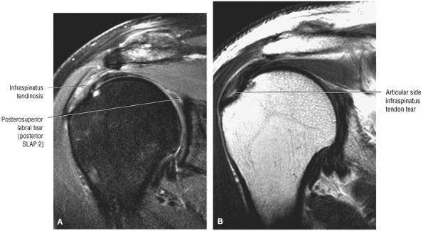 |
|
FIGURE 8.291 ● Coronal FS PD FSE (A) and T2 FSE (B) images of posterior peel-back lesion with a tear of the posterosuperior labrum associated with an articular-side posterior cuff partial tear.
|
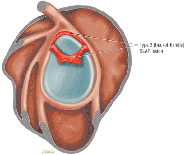 |
|
FIGURE 8.292 ● Lateral color illustration of a type 3 SLAP lesion with bucket-handle tear. The superior labrum may be meniscoid. The biceps tendon attachment is intact. The bucket fragment may be split into two fragments and/or inferiorly displaced from the biceps anchor on MR images.
|
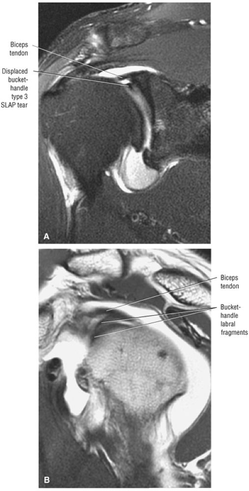 |
|
FIGURE 8.293 ● The “three structure sign” corresponding to the biceps tendon superior to the two bucket-handle components of the superior labrum on (A) a coronal FS PD FSE MR arthrogram and (B) a sagittal PD FSE MR arthrogram.
|
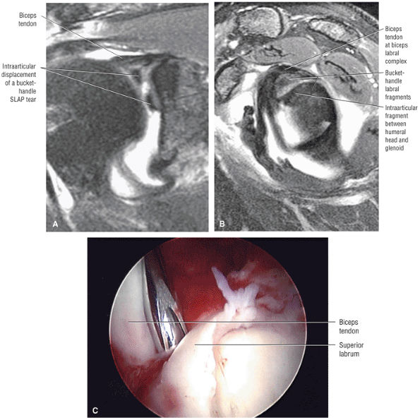 |
|
FIGURE 8.294 ● (A, B) Intra-articular displacement of a bucket-handle superior labral tear in a SLAP 3 associated with a Bankart lesion (a SLAP 5 equivalent). (A) Coronal FS PD FSE. (B) Sagittal FS PD FSE. (C) Arthroscopic view of type 3 SLAP tear at the superior pole of the glenoid. There is separation from the biceps anchor at the probe site in this bucket-handle tear.
|
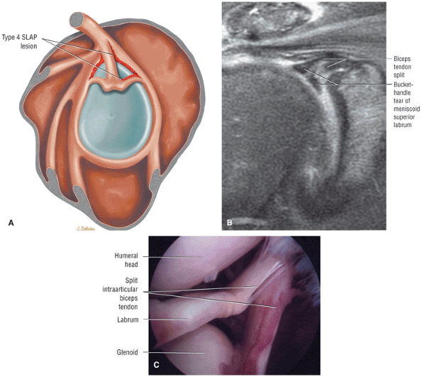 |
|
FIGURE 8.295 ● (A) Lateral color graphic illustrating a SLAP 4 lesion with a split or bucket-handle tear of the superior labrum that continues into the biceps tendon. (B) Coronal FS PD FSE image with bucket-handle tear and split of the intra-articular biceps. (C) Arthroscopic view of type 4 SLAP with extension of the superior labral tear into the biceps root.
|
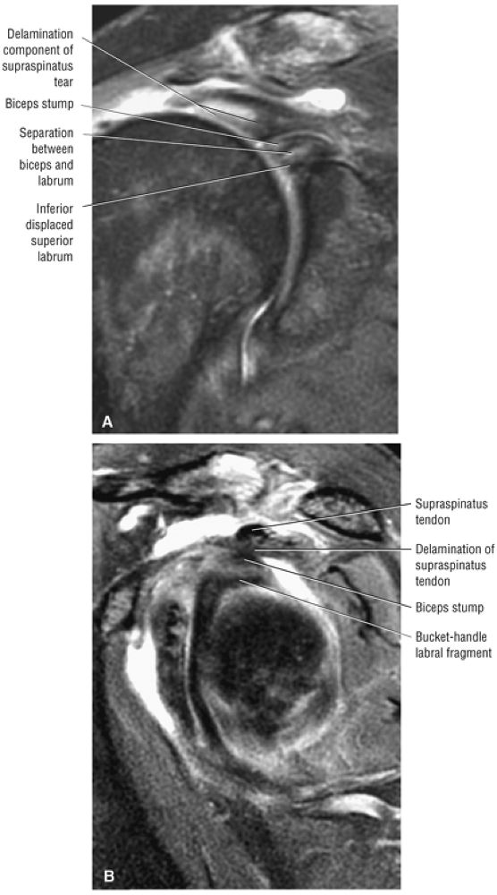 |
|
FIGURE 8.296 ● (A) Coronal FS PD FSE and (B) sagittal FS PD FSE images of a SLAP 4 lesion with associated rupture of the intra-articular biceps. The intra-articular biceps stump is visible superior to the superior labrum.
|
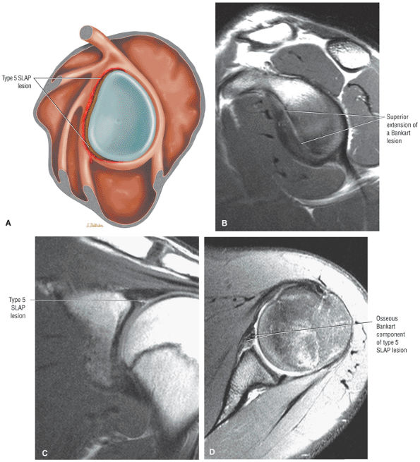 |
|
FIGURE 8.297 ● Type 5 SLAP lesion with superior extension of a Bankart lesion into a superior SLAP lesion. The superior labral lesion may be type 2 or 3. (A) Lateral color illustration with anterosuperior and anteroinferior SLAP 5 extension. (B) Sagittal PD FSE image showing an extensive anterior labral tear. (C) Coronal PD FSE image of inferior displacement of the superior labrum. (D) Axial FS PD FSE image of an anterior labral soft tissue Bankart lesion.
|
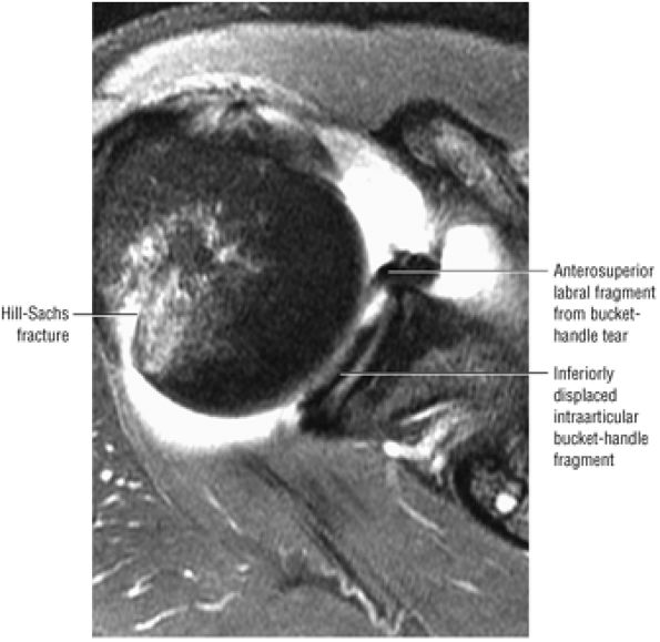 |
|
FIGURE 8.298 ● An axial FS PD FSE image displaying a SLAP 5 lesion with an associated posterolateral Hill-Sachs humeral head fracture. Superior glenohumeral joint entrapment of bucket-handle labral fragments is visualized in the same axial section.
|
-
SLAP 1 lesions are a normal finding.
-
SLAP 2 lesions occur in traction injuries with forced extension on a flexed forearm.
-
In 31% of cases, SLAP 3, 4, or 5 lesions are associated with a fall on an outstretched hand.
-
Anterior dislocation is often associated with SLAP 5 lesions.
-
A bare labral footprint
-
A sublabral sulcus greater than 5 mm (measured between the superior labrum and the superior pole of the glenoid)
-
A displaceable biceps (biceps root rolls over the glenoid)
-
Associated effects of SLAP lesions include:
-
Biceps anchor disruption between the intra-articular biceps and the superior labrum with or without associated intralabral tearing (The superior labrum may be directly avulsed from the superior glenoid articular cartilage in a type I BLC.)
-
Increased humeral head translation in microinstability
-
Strain of humeral head restraints
-
Glenohumeral laxity and/or instability
-
Paralabral cysts (commonly associated with type 2 SLAP lesion)
-
SLAP fracture227 with a superior humeral head chondral fracture and a SLAP (Fig. 8.305) lesion
-
SLAP fracture avulsion (Fig. 8.306) from the superior pole of the glenoid (rare)
-
-
A type 1 SLAP lesion is treated with arthroscopic débridement of the degenerative labrum.
-
Treatment of a type 2 SLAP lesion (which involves detachment of the superior labrum and biceps anchor) addresses the avulsed labrum and reattachment of the detached biceps anchor to the superior glenoid (Fig. 8.307). A suture anchor technique, for example, may be used for a type 2 SLAP tear.
-
Since there is no involvement of the biceps anchor in a type 3 SLAP lesion (a bucket-handle tear and a meniscoid-type superior labrum), arthroscopic débridement of the loose labral fragment may be sufficient to relieve symptoms of catching and snapping.
-
A type 4 SLAP lesion, which also involves a bucket-handle tear associated with a meniscoid-type superior labrum, additionally extends into the biceps tendon. Treatment of type 4 lesions ranges from resection of torn tissue to suture repair for bucket-handle tears associated with more extensive involvement of the biceps tendon.
-
Types 5 through 10 SLAP lesions require restoration of normal anatomy, including the MGHL and IGHLC. The labrum is stabilized and reattached.
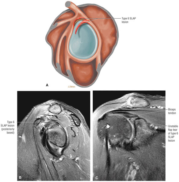 |
|
FIGURE 8.299 ● (A) Lateral color illustration, (B) sagittal FS PD FSE image, and (C) coronal FS PD FSE image of posterior-based superior flap SLAP 6 lesion. The sagittal plane is required for direct visualization of the flap morphology; otherwise, the coronal MR appearance is similar to a bucket-handle tear.
|
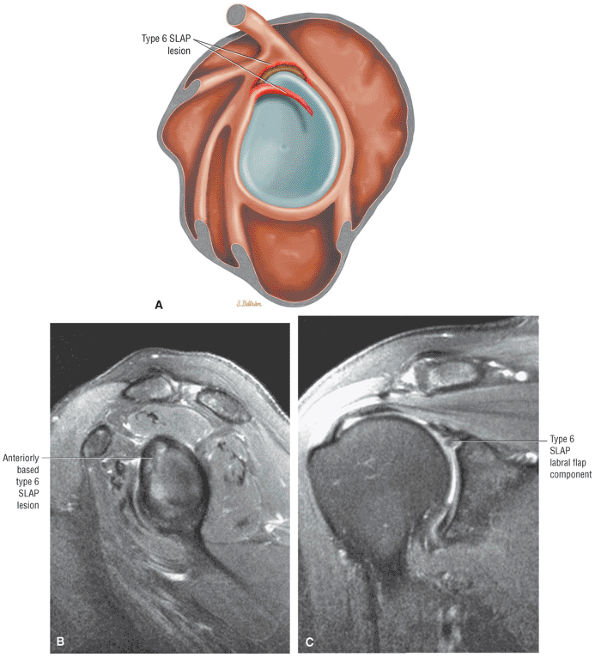 |
|
FIGURE 8.300 ● (A) Lateral color graphic, (B) sagittal FS PD FSE image, and (C) coronal FS PD FSE of anterior-based superior flap tear of a SLAP 6 lesion.
|
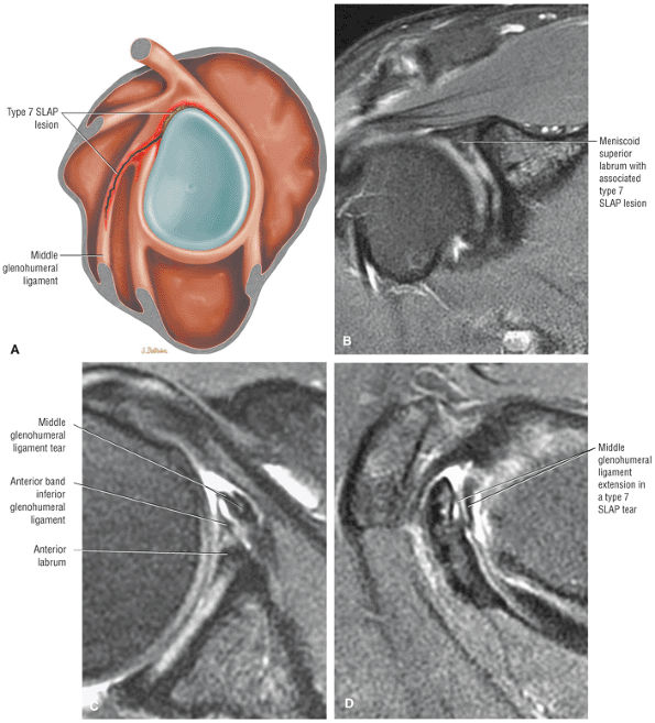 |
|
FIGURE 8.301 ● (A) Lateral color illustration of a SLAP 7 lesion with extension of a superior SLAP 2 or 3 into the middle glenohumeral ligament (MGL). (B) Coronal FS PD FSE image demonstrates anterior extension of a SLAP tear toward the MGL. (C) Axial T2*-weighted GRE image with fragmentation of the MGL. Normal MGL laxity with ligament redundancy may falsely appear as a torn ligament on axial images. Therefore, confirmation of pathology requires proper correlation with sagittal images. (D) Confirmation of MGL involvement on a sagittal FS PD FSE image.
|
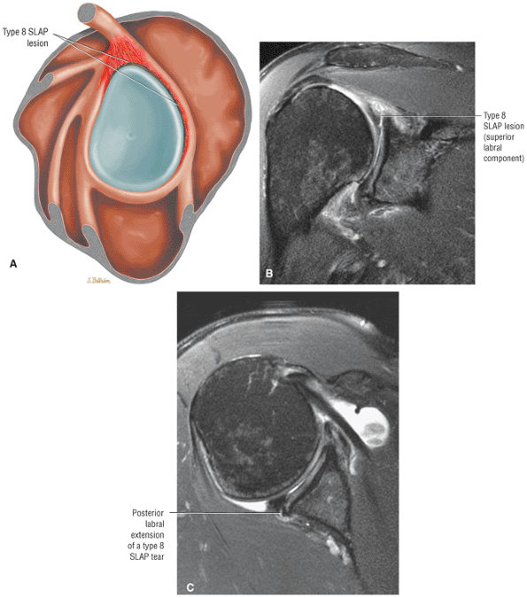 |
|
FIGURE 8.302 ● (A) Lateral (sagittal) color illustration of a type 8 SLAP with extension of a SLAP 2 to involve the posterior labrum. (B) Coronal FS PD FSE image with a SLAP 2 component and paralabral cyst as part of the SLAP 8 lesion. (C) Axial FS PD FSE image documents posterior labral tear extension from the biceps labral complex.
|
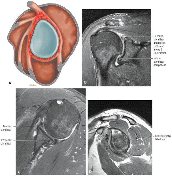 |
|
FIGURE 8.303 ● (A) Lateral color graphic of a type 9 SLAP lesion with circumferential labral tearing of all glenoid quadrants. (B) Coronal FS PD FSE image with a type 2 SLAP at the BLC and an inferior labral tear at the 6-o—clock position of the inferior pole. (C) Corresponding axial FS PD FSE image with anterior and posterior labral tears. (D) Sagittal PD FSE image of circumferential labral tear (around the entire glenoid “clock” tear). There is usually associated glenoid rim sclerosis.
|
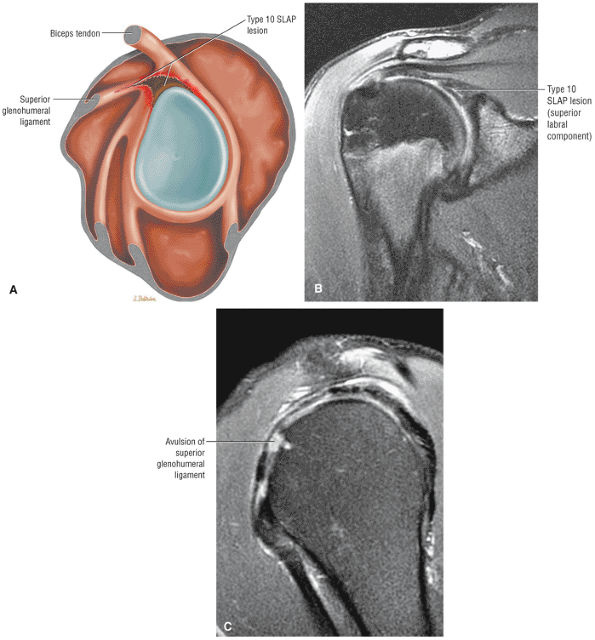 |
|
FIGURE 8.304 ● (A) A SLAP 10 lesion with associated rotator cuff interval involvement shown with extension in the superior glenohumeral ligament on a lateral glenoid color illustration. (B) Coronal FS PD FSE image with SLAP 2 component of the SLAP 10 lesion. (C) Sagittal FS PD FSE image with associated rupture of the superior glenohumeral ligament.
|
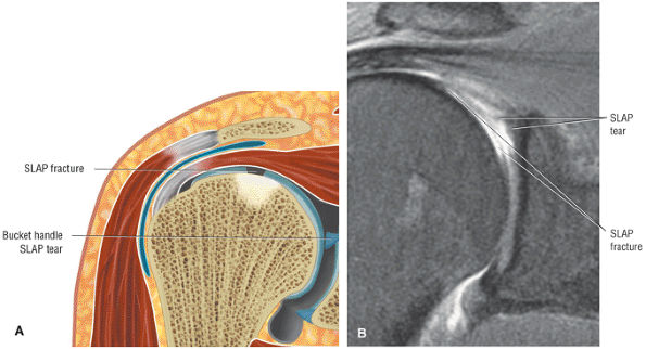 |
|
FIGURE 8.305 ● (A) Coronal color illustration and (B) coronal FS PD FSE image of a SLAP fracture with a chondral divot of the superior humeral head. This type of injury is caused by impaction, often occurring in the setting of a fall onto an outstretched arm that drives the humeral head against the superior labrum and biceps anchor. These chondral fractures are more anterior and medial than the posterolateral Hill-Sachs anterior instability lesion. The SLAP fracture is frequently associated with a type 3 or 4 SLAP lesion, especially in the presence of a meniscoid-type superior labrum, which is more susceptible to injury.
|
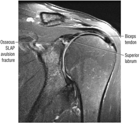 |
|
FIGURE 8.306 ● Coronal FS PD FSE image showing the unusual SLAP 2 avulsion fracture. This type of fracture is seen with osseous avulsion of the biceps and labrum from the superior glenoid as the biceps tendon is stretched over the humeral head during a fall onto an outstretched arm. The avulsion-type fracture is rare relative to the humeral head dome chondral “SLAP fracture.”
|
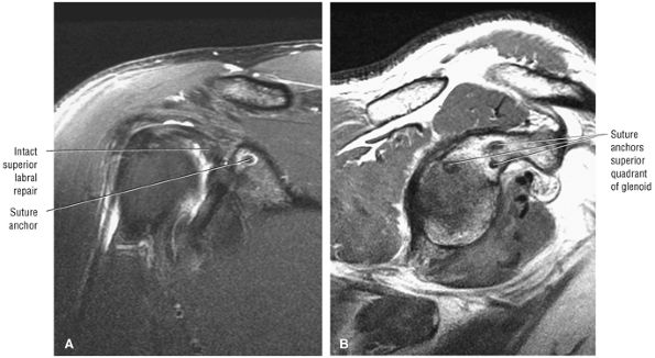 |
|
FIGURE 8.307 ● (A) Coronal FS PD FSE and (B) sagittal PD FSE images of a SLAP lesion treated with superior quadrant suture anchors. SLAP lesions have also been treated by a single-anchor, double-suture SLAP repair to form a sling around the biceps anchor. Techniques that drill across the glenoid or through the acromion or use an absorbable tacking device are less successful and may lead to implant failure, synovitis, and intra-articular loose fragments.
|
-
The coronal oblique plane is used to assess both the superior labrum at the superior pole of the glenoid and the IGLLC at the inferior pole of the glenoid.
-
The sagittal oblique plane is useful in identifying normal variations in the MGHL and the anterior band of the IGHL relative to the corresponding morphology of the anterior labrum in the axial plane. The sagittal oblique plane demonstrates bucket-handle SLAP tear patterns.
-
The labrum usually tears in an entire quadrant on more than one image location.
they are not directly related to nor do they contribute to shoulder instability. Complex labral tears and the location of the labral segments involved can be correlated between sagittal oblique and axial images.
-
Type 1 SLAP lesion. Superior labral degeneration in a SLAP 1 lesion may be difficult to appreciate. The degeneration and fraying display increased signal intensity in T2*-weighted images, and morphologic irregularities may be appreciated with MR arthrography with intra-articular contrast. There is no labral detachment in SLAP 1 lesions.
-
Type 2 SLAP lesions demonstrate increased signal intensity, which undermines the superior labral base, on FS PD FSE images or MR arthrography. This may communicate with a superior glenoid labral cyst. Separation of the superior labrum from the glenoid rim increases the specificity of differentiating a type 2 SLAP lesion from a sublabral foramen. A sublabral foramen is located more anteriorly within the anterior superior quadrant, in comparison with the more superior position of the SLAP lesion, which is centered on the superior pole of the glenoid in the region of the BLC. Sagittal oblique images may be helpful in confirming fluid signal intensity crossing the base of the superior labrum or biceps anchor. Associated synovitis with effacement of fat may be seen between the coracoid and the anterior superior glenoid rim in acute or subacute SLAP lesions. A sublabral foramen should not demonstrate associated synovitis. We have observed intravenous MR contrast enhancement of synovial tissue and fat anterior to the superior labrum in cases of capsular strain without associated labral pathology. The SLAP 2 lesion should be carefully inspected for true anterior-to-posterior extension.253 For example, a posterior subtype of SLAP 2 (posterior peel-back lesion) does not demonstrate anterior extension within the superior labrum of the BLC. The SLAP lesion may occur within the labrum at the biceps tendon–labrum attachment or between the labrum and the superior pole of the glenoid in cases of type 1 BLC (the BLC is firmly adherent to the articular cartilage of the superior pole of the glenoid). Under forcible excessive humeral rotation, a normal preexisting biceps labral sulcus can develop into a pathologic type 2 SLAP lesion.254
P.1407
Distinguishing between a normal sulcus and a type 2 SLAP requires consideration of secondary and associated findings of a SLAP tear, including:-
Superior displacement of the labrum
-
Increased depth of the sulcus
-
Synovitis
-
Adjacent labral and chondral fraying
-
Micro-paralabral (early) cyst formation
-
-
Type 3 and type 4 SLAP lesions and bucket-handle tears. Sagittal images are particularly useful in identifying bucket-handle lesions and types 3 and 4 SLAP lesions with a bucket-handle tear. Extension of the tear into the biceps anchor (type 4) is best depicted in the sagittal oblique plane. Displaced labral tissue in types 3 and 4 SLAP lesions is seen as low-signal-intensity fragments within the glenohumeral joint on both axial and coronal oblique images. A bucket-handle type labral tear is characterized by a torn superior labrum, visualized as two separate sections on coronal images through the BLC. The MR visualization of fluid between two fragments of the superior labrum lateral to the biceps labral sulcus has been referred to as the double “Oreo cookie” configuration.237 However, we recommend avoiding this terminology. Inferior displacement of the superior labrum, or a portion of the superior labrum, from its biceps attachment is associated with a displaced bucket-handle tear. Signal intensity seen between the biceps tendon and labrum indicates the presence of a SLAP lesion. Type 3 and type 4 SLAP tears demonstrate an additional hypointense labral structure on sagittal images through the biceps labral complex (the triple structure sign of a displaced SLAP tear). Three separate and distinct structures may also be appreciated on coronal images when there is fluid between the biceps tendon and the superior labrum and fluid between two separated labral fragments.
-
Type 5 SLAP lesions. In type 5 SLAP the anterior labrum is torn in continuity with the SLAP tear (associated type 2 or type 3). The Bankart component is identified on axial images, whereas the SLAP region is visualized in the coronal plane.
-
Type 6 SLAP lesions. The type 6 SLAP is best identified on coronal images, although sagittal images are required to appreciate the flap component.
-
Type 7 SLAP lesions. Caution should be used in diagnosing a type 7 SLAP lesion because on axial images the two separate portions of a normal lax MGHL may mistakenly appear like a torn ligament.
-
Type 8 SLAP lesions. Type 8 SLAP lesions involve the posterosuperior and posteroinferior labrum in continuity with a SLAP 2 tear. Axial and sagittal images display the extent of posterior labral involvement.
-
Type 9 SLAP lesions. Coronal images display superior and inferior labral tearing in type 9 SLAP. Axial images demonstrate anterior and posterior labral tearing, and sagittal images show circumferential tearing with or without associated glenoid rim sclerosis.
-
Type 10 SLAP lesions. The type 10 SLAP tear presents as a SLAP lesion plus injury to the biceps pulley associated with medial subluxation of the biceps tendon (medial relative to the bicipital groove). Sagittal images demonstrate pathology of the superior glenohumeral ligament, whereas axial images are used to assess medial subluxation (instability) of the biceps tendon.
-
In type 1, there is increased signal intensity within the labrum but no surface extension. Type 1 corresponds to internal labral degeneration without tear.
-
In type 2, the blunted or frayed labrum demonstrates normal dark signal intensity.
-
In type 3, T1-weighted or T2*-weighted images demonstrate increased signal intensity that extends to the surface, indicating a labral tear.
-
In type 4, a labral tear is depicted by a combination of abnormal morphology with type 2 features and increased signal intensity extending to the surface of the labrum with type 3 features.
for detached labral fragments. Gadolinium-enhanced MR imaging allows the spatial detection of avulsed labral tissue relative to the glenoid rim. Labral tears are usually highlighted on FS T1-weighted images following intra-articular gadolinium administration. A synovial shelf in the subscapularis bursa is a normal finding sometimes seen on enhanced studies.260 Normal intermediate-signal-intensity fibrocartilage at the base of the anterior labrum does not show extension of contrast with MR arthrography. MR arthrography has also been shown to be accurate in the evaluation of chronic labral tears.261
-
Paralabral cysts frequently communicate with a SLAP 2 or posterior-type SLAP 2 lesion.
-
A paralabral cyst usually coexists with a labral tear but may be associated with degenerative arthritis.
-
Suprascapular notch cysts are associated with edema or atrophy of the supraspinatus and infraspinatus.
-
Spinoglenoid notch cysts are associated with edema or atrophy of the infraspinatus.
-
Inferior paralabral cysts are associated with isolated denervation of the teres minor muscle.
-
Associated with the biceps labral complex in continuity with a SLAP 2 or posterior peel-back type SLAP 2 lesion involving the posterior superior labrum
-
The anterior labrum
-
The posterior labrum
-
The inferior labrum (Fig. 8.308)
-
Complex (anterior and posterior) paralabral cysts may be associated with multiple locations (Fig. 8.309).
-
Paralabral cysts that extend to the spinoglenoid notch can produce atrophy of the infraspinatus and/or the supraspinatus muscles secondary to suprascapular nerve entrapment (see discussion below).262,263,264
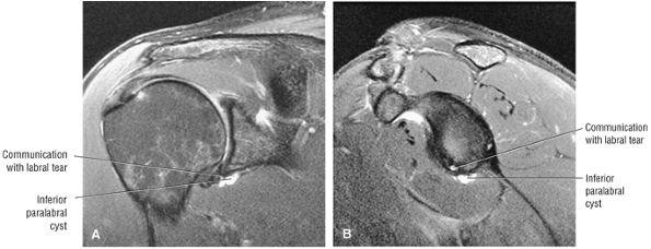 |
|
FIGURE 8.308 ● (A) Coronal FS PD FSE and (B) sagittal FS PD FSE images of an inferior paralabral cyst communicating with an anteroinferior-to-inferior labral tear.
|
(inferior transverse scapular ligament) is variably present and is located superior to the suprascapular nerve.
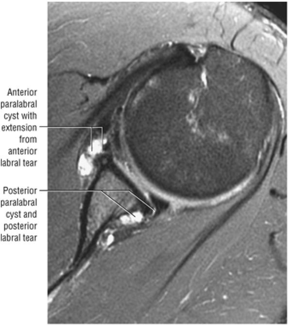 |
|
FIGURE 8.309 ● Axial FS PD FSE image showing anterior and posterior paralabral cysts communicating with their respective labral tears.
|
-
Suprascapular nerve compression syndrome (pain and weakness of supraspinatus and infraspinatus muscles)
-
SLAP lesions with associated anterosuperior, posterosuperior, or combined paralabral cysts
-
Posterosuperior labral tears associated with spinoglenoid notch cysts, presenting as a deep ache or muscle tightness in the shoulder with progressive weakness
-
Axillary nerve compression (weakness of the deltoid and teres minor associated with axillary nerve denervation), when the cyst extends inferiorly and dissects into the quadrilateral space
-
Isolated teres minor muscle denervation (when the teres minor branch of the axillary nerve, which is closest in proximity to the axillary pouch of IGHL, is compressed by an inferior paralabral cyst; also see discussion of the quadrilateral space syndrome below)
-
Clicking or catching with pain in the cocking and acceleration phase of throwing (a deep ache in the posterior shoulder with progressive weakness indicates nerve compression)
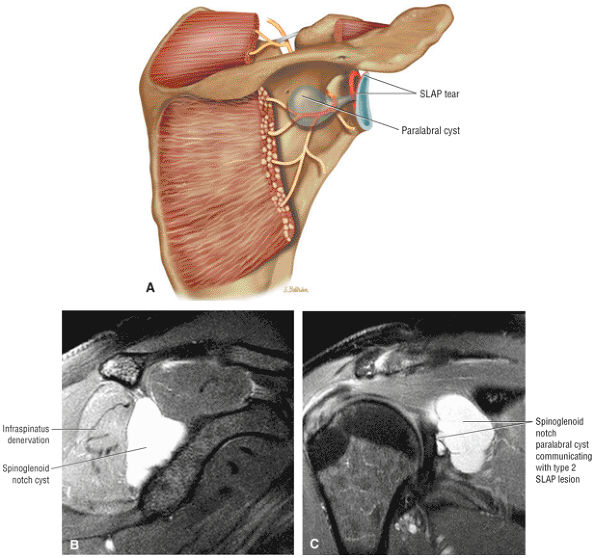 |
|
FIGURE 8.310 ● (A) Posterior coronal color illustration, (B) sagittal FS PD FSE image, and (C) coronal FS PD FSE image illustrate a spinoglenoid notch cyst in communication with a SLAP 2 tear and causing compression of the suprascapular nerve.
|
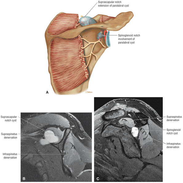 |
|
FIGURE 8.311 ● (A)Posterior coronal color graphic illustrating the combined denervation of the supraspinatus and infraspinatus muscles associated with paralabral cyst involvement affecting both the suprascapular notch anteriorly and the spinoglenoid notch posteriorly.MR characteristics can be seen on sagittal FS PD FSE images at the level of the suprascapular notch(B)and the spinoglenoid notch(C 0)
|
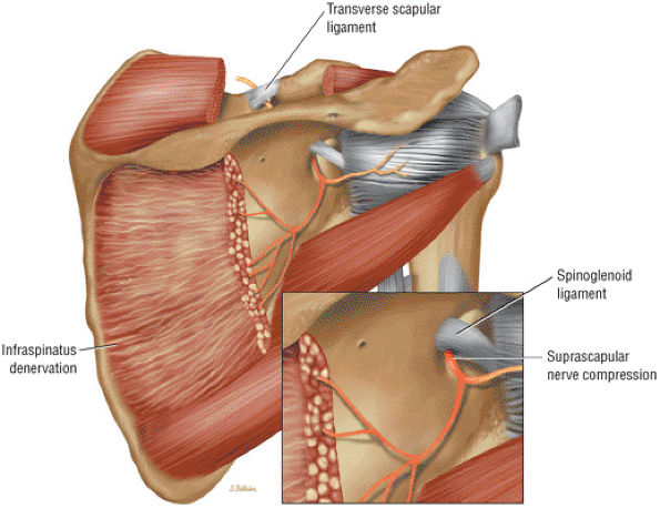 |
|
FIGURE 8.312 ● Selective or isolated infraspinatus denervation secondary to compression by a thickened spinoglenoid ligament. The suprascapular nerve and artery enter the supraspinatus fossa through the scapular notch by passing deep to the transverse scapular ligament. The suprascapular nerve enters the infraspinatus fossa by coursing lateral to the spinoglenoid notch. The lateral margin of the spinoglenoid notch is created by the fibrous band called the spinoglenoid ligament. The suprascapular nerve is relatively immobile in this area and thus susceptible to injury or compression by paralabral cysts. In extreme abduction and external rotation (in the throwing athlete, for example), the medial tendinous margin of the supraspinatus and infraspinatus can impinge against the lateral edge of the scapular spine. This results in compression of the infraspinatus branch of the suprascapular nerve. Painless atrophy of the infraspinatus muscle in volleyball players (attribu-ted to contraction of the infraspinatus muscle during the volleyball serving action) involves neuropathy of the inferior branch of the supra-scapular nerve.
|
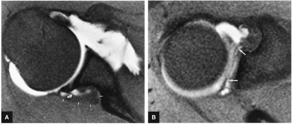 |
|
FIGURE 8.313 ● T1 FS axial MR arthrograms of paralabral cyst. (A) Partial filling (curved arrow) of a spinoglenoid notch cyst (small straight arrows) with intra-articular contrast. (B) Communication of the cyst with a SLAP type 2 lesion. The superior labrum is torn from anterior to posterior (arrows) as assessed on the axial image through the most superior aspect of the glenohumeral joint.
|
-
Trauma with a fall on the shoulder
-
Traction injury
-
Weightlifting (which is also associated with traction injury to the teres minor nerve branch of the axillary nerve, even in the absence of an inferior paralabral cyst)
-
Sports emphasizing an overhead motion
-
The posterior branch of the axillary nerve courses adjacent to the inferior pole of the glenoid and inferior joint capsule and then divides into a branch to the teres minor muscle and a superolateral brachial cutaneous nerve branch.
-
The quadrilateral space syndrome is more commonly associated with denervation edema or atrophy restricted to the teres minor muscle, although the teres minor and deltoid are both supplied by the axillary nerve.
-
Proximal humeral and scapular fractures
-
Posttraumatic fibrous bands
-
Masses, including teres minor hypertrophy and lipomas (Fig. 8.315)
-
Inferior labral tears with dissecting paralabral cysts
-
Lipomatous masses
-
Enlarged veins extending into the quadrilateral space
-
Parsonage-Turner syndrome is characterized by acute painful brachial neuritis.
-
Supraspinatus and infraspinatus; supraspinatus, infraspinatus, and deltoid; and infraspinatus and teres minor are potential patterns of affected muscle groups.
-
FS PD FSE images show all hyperintense muscles involved in the sagittal plane.
nontraumatic neuropathy involving an idiopathic denervation syndrome of the shoulder girdle musculature.272 More than one nerve distribution may be involved, with denervation typically affecting mainly the lower motor neurons of the brachial plexus and/or individual nerves or nerve branches. The etiology is related to an immune-mediated inflammatory reaction against nerve fibers. Infection, surgery, trauma, childbirth, vaccinations, and systemic illness are all possible causes. In an associated rare digital form, the forearm, wrist, and hand may be involved. Denervation and swelling within the affected muscles are found in the early and subacute phase, which lasts 3 to 6 months. Fatty atrophy is seen in the chronic phase. Age range spans from 3 months to 74 years, with the majority of cases lasting up to 1 year. There is a 2 to 4:1 male predominance. Bilateral involvement may occur in up to one third of patients. Residual denervation is present in 10% to 20% of cases after 2 years.
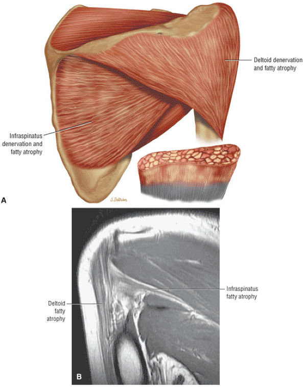 |
|
FIGURE 8.314 ● Quadrilateral space syndrome with denervation and fatty atrophy of the teres minor and deltoid in the throwing athlete. (A) Coronal illustration of teres minor and deltoid fatty atrophy. The axillary nerve is susceptible to entrapment by fibrous bands in the quadrilateral space when the arm is abducted externally rotated. Selective involvement of the teres minor with posterior pain and tenderness may be present. (B) Coronal PD FSE image of fatty atrophy of both the deltoid and teres minor muscle groups.
|
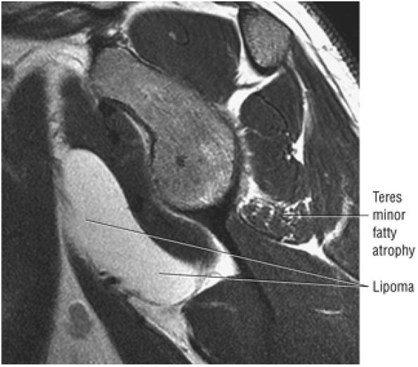 |
|
FIGURE 8.315 ● Sagittal PD FSE image of the quadrilateral space syndrome with isolated fatty atrophy of the teres minor associated with a space-occupying lipoma demonstrating fat signal intensity. The quadrilateral space, which contains the axillary nerve and posterior circumflex humeral artery, is bordered by the inferior border of the teres minor superiorly, the teres major inferiorly, the long head of the triceps brachii muscle medially, and the diaphysis of the humerus laterally.
|
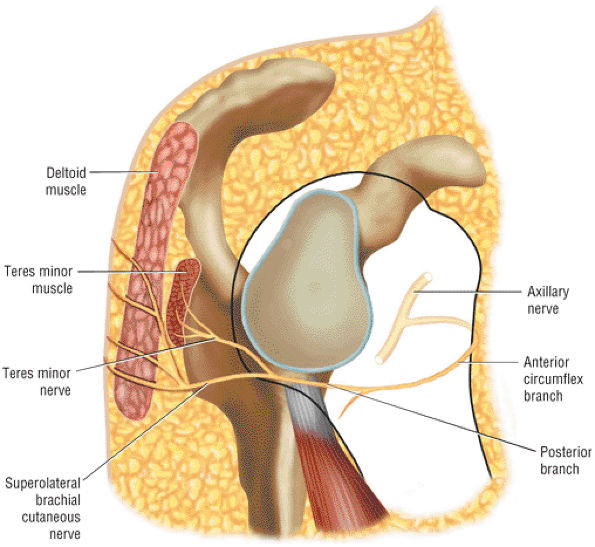 |
|
FIGURE 8.316 ● The normal course of the posterior branch of the axillary nerve, which divides into the nerve to the teres minor and a superolateral cutaneous nerve branch.
|
-
Supraspinatus and infraspinatus muscles affected, indicating suprascapular nerve involvement (Fig. 8.318)
-
Supraspinatus, infraspinatus, and deltoid muscles affected, indicating suprascapular and axillary nerve involvement (Fig. 8.319)
-
Infraspinatus and teres minor muscles affected, indicating suprascapular and axillary nerve involvement (Fig. 8.320)
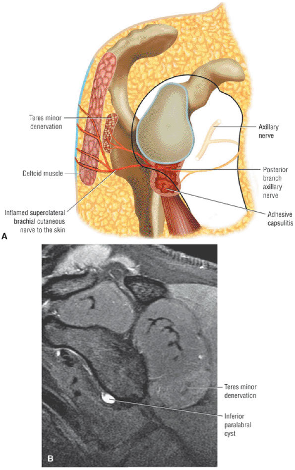 |
|
FIGURE 8.317 ● (A) Teres minor denervation related to inferior capsular adhesive capsulitis. The thickened and inflamed inferior capsule is adjacent to the posterior branch of the axillary nerve. (B) Inferior paralabral cyst associated with teres minor hyperintensity on a sagittal FS PD FSE image.
|
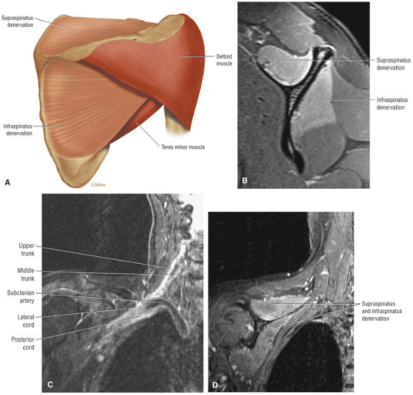 |
|
FIGURE 8.318 ● (A) Parsonage-Turner syndrome with denervation of the supraspinatus and infraspinatus muscles. (B) Sagittal FS PD FSE image with uniform supraspinatus and infraspinatus denervation without any associated suprascapular notch mass. The involvement of the supraspinatus and infraspinatus in idiopathic denervation is a common presentation of Parsonage-Turner. (C) Brachial plexus neuritis with hyperintensity of the upper and middle trunks. The suprascapular nerve is derived from the upper (superior) trunk. The upper or superior trunk is formed by the upper two roots (C5, C6). The brachial plexus network originates from the anterior primary rami of the C5 to T1 spinal nerves. (D) Corresponding coronal FS PD FSE sequence shows supraspinatus and infraspinatus denervation related to Parsonage-Turner syndrome as an acute brachial neuritis.
|
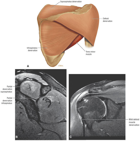 |
|
FIGURE 8.319 ● (A) Color posterior coronal illustration of Parsonage-Turner variation with denervation of the supraspinatus, infraspinatus, and deltoid (suprascapular and axillary nerve innervation). Sagittal (B) and coronal (C) FS PD FSE images showing subtle changes of Parsonage-Turner syndrome with denervation hyperintensity of the deltoid, supraspinatus, and infraspinatus muscles (B) and the deltoid muscle (C).
|
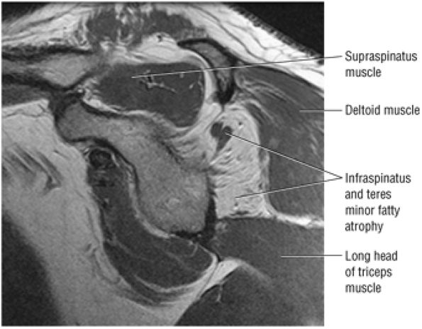 |
|
FIGURE 8.320 ● Chronic Parsonage-Turner syndrome with history of bilateral involvement. Fatty atrophy is demonstrated in the infraspinatus and teres minor on this sagittal PD FSE image. Parsonage-Turner syndrome is not usually associated with muscle fatty infiltration but more commonly demonstrates muscle atrophy with decreased muscle bulk.
|
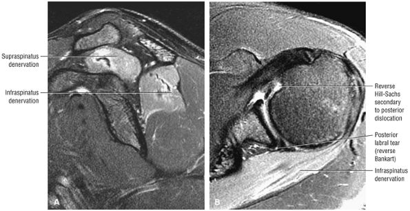 |
|
FIGURE 8.321 ● Posterior dislocation with suprascapular neurapraxia affecting the supraspinatus and infraspinatus muscles is seen on sagittal (A) and axial (B) FS PD FSE images. The MR appearance of supraspinatus and infraspinatus distribution could mimic Parsonage-Turner syndrome. The axillary nerve is usually at risk in anterior dislocations.
|
-
The biceps tendon origin includes the posterosuperior labrum and supraglenoid tubercle medial to the BLC.
-
The CHL-SGHL complex and not the transverse humeral ligament provides the stability of the biceps tendon in the intertubercular sulcus (groove).
-
Intra-articular biceps tendinosis may be overestimated on sagittal images secondary to the magic-angle effect.
-
Biceps tenosynovitis is visualized with hyperintense fluid or intermediate to hyperintense signal in the presence of thickened synovium.
-
Biceps tendon ruptures occur at the biceps anchor or within the rotator cuff interval.
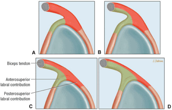 |
|
FIGURE 8.322 ● Variation in the biceps tendon contribution to the BLC. These variations include an exclusive contribution to the posterosuperior labrum (A); a primary contribution to the posterosuperior labrum and secondary involvement of the anterosuperior labrum (B); equal contribution to the anterosuperior and posterosuperior labrum (C); and a primary contribution to the anterosuperior labrum and secondary contribution to the posterosuperior labrum (D).
|
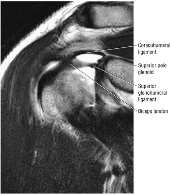 |
|
FIGURE 8.323 ● Coracohumeral and superior glenohumeral ligaments coursing laterally toward the entrance of the intertubercular groove, forming the stabilizing biceps pulley within the rotator cuff interval as seen on a coronal T2 FSE image.
|
-
Rheumatoid arthritis
-
Osteoarthritis (or osteochondromatosis of the shoulder and biceps tendon sheath)
-
Hemodialysis arthropathy
-
Crystalline arthritis (Fig. 8.327)
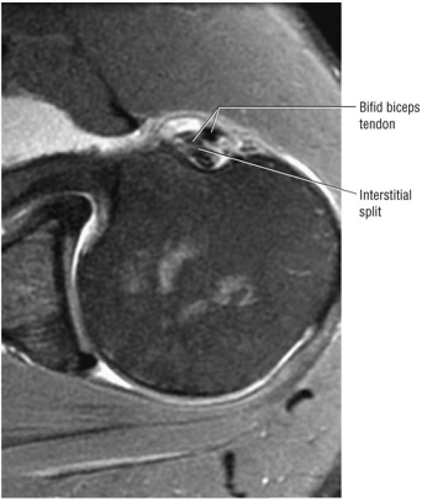 |
|
FIGURE 8.324 ● Axial FS PD FSE image showing the bifid biceps tendon with interstitial split of the posterior extra-articular component.
|
-
Pulley lesions of the rotator interval
-
Anterosuperior impingement (ASI)
-
Posterior peel-back lesions in throwing athletes
-
SLAP lesions
-
Biceps tenosynovitis
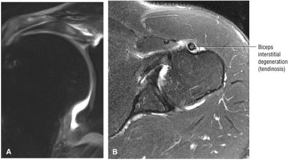 |
|
FIGURE 8.325 ● (A) Biceps tendinosis with thickening and increased signal intensity within the substance of the intra-articular biceps can be seen on this coronal FS PD FSE image. (B) Extra-articular biceps tendon with interstitial degeneration is seen on this axial FS PD FSE image.
|
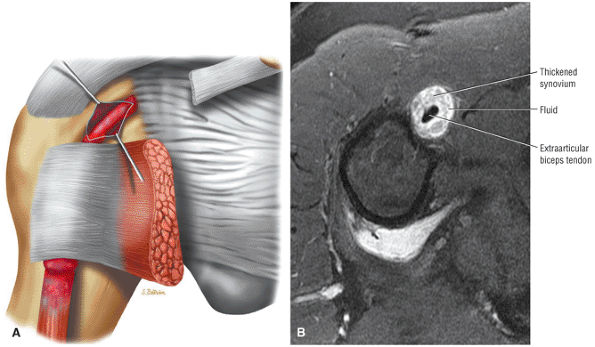 |
|
FIGURE 8.326 ● (A) Biceps tenosynovitis with inflammation of the proximal biceps tendon sheath. A positive Speed—s test (downward force applied to the arm with the elbow extended and forearm supinated) with upper anterior arm and shoulder pain is associated with biceps tendon inflammation. (B) Axial FS PD FSE image showing thickened intermediate synovium with hyperintense fluid surrounding the biceps tendon in severe tenosynovitis.
|
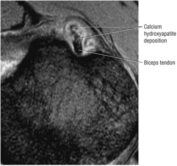 |
|
FIGURE 8.327 ● Calcium hydroxyapatite deposition involving the proximal biceps sheath. Calcific tendinitis may involve the biceps at its attachment to the superior pole of the glenoid or distal to the glenohumeral joint at the junction of the tendon and muscle. Small deposits are characteristic at the level of the proximal humeral diaphysis and occur anterior, medial, or lateral to the biceps tendon, as seen on this axial T2* GRE image.
|
-
Type A is impingement tendinitis.
-
Type B is subluxation and/or dislocation of the biceps tendon.
-
Type C is attritional tendinitis.
-
The biceps origin
-
The rotator interval
-
The rotator cuff (lesions associated with rotator cuff tears)
-
Type 1 is tendon rupture without retraction.
-
Type 2 is tendon rupture with partial recession.
-
Type 3 is a self-attaching rupture without retraction.
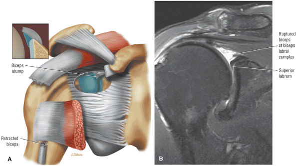 |
|
FIGURE 8.328 ● (A) Coronal anterior view color illustration of rupture of the intra-articular biceps at the BLC adjacent to the biceps anchor. (B) Coronal FS PD FSE image with biceps rupture at the supraglenoid tubercle.
|
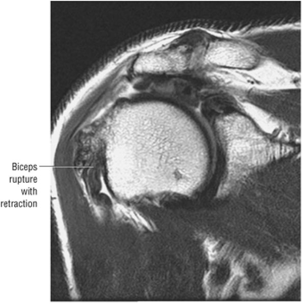 |
|
FIGURE 8.329 ● Rupture of the biceps with retraction. The edge of the torn biceps tendon is visualized as a redundant structure in the groove. Coronal T2 FS MR is especially useful in distinguishing between retraction and partial recession (retraction) from a self-attaching but non-retracted biceps.
|
-
Reversible tendon change with less than 25% partial-thickness tear from a normal width biceps tendon. The biceps tendon size and groove location are normal.
-
Irreversible tendon change with partial-thickness tear or fraying of greater than 25% of the normal biceps tendon width. There is associated biceps subluxation and disruption of the bicipital groove osseous or ligamentous anatomy.
and the discontinuity of the intra-articular biceps tendon can be displayed on MR images (Fig. 8.332).
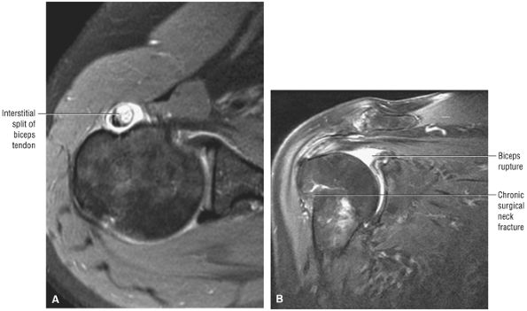 |
|
FIGURE 8.330 ● (A) Severe interstitial split of the biceps tendon involving the extra-articular course of the tendon split is hyperintense on this axial FS PD FSE image. (B) Biceps tendon rupture and retraction associated with chronic proximal humeral surgical neck fracture are seen on a coronal FS PD FSE image.
|
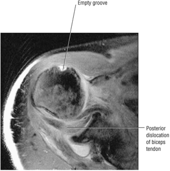 |
|
FIGURE 8.331 ● Axial FS PD FSE image of posterior dislocation of the biceps tendon posterior to the humeral head and biceps labral complex. There is an associated complete rupture of the rotator cuff. The bicipital groove is empty and the biceps tendon is posteriorly directed relative to the humeral head and entrapped.
|
-
Acute adhesive capsulitis demonstrates a hyperintense and thickened IGHL on coronal FS PD FSE images. Associated synovial hypertrophy is shown as intermediate signal intensity and occupies the space created by the axillary pouch.
-
Residual or chronic thickening of the axillary pouch does not demonstrate hyperintensity on coronal FS PD FSE images.
-
Adhesive capsulitis may coexist with synovitis in other joint locations, including the rotator cuff interval and subscapularis recess.
-
The axillary nerve is susceptible to injury during transection of the axillary pouch in arthroscopic treatment of adhesive capsulitis. Arthroscopic capsular release should be considered when conservative management or manipulation is unsuccessful.
passive shoulder and scapulothoracic motion. Symptoms are usually present for at least 1 month, and the clinical course can be divided into stable or progressive categories. Adhesive capsulitis is either primary (idiopathic), with no predisposing history or cause, or secondary, with an antecedent event such as trauma or previous surgery. Inflammation of the inferior shoulder capsule also causes a limited range of motion or a frozen shoulder. The association of adhesive capsulitis with other shoulder disorders, such as impingement, represents secondary adhesive capsulitis. The etiology of secondary adhesive capsulitis can be further subdivided into the following causes:283
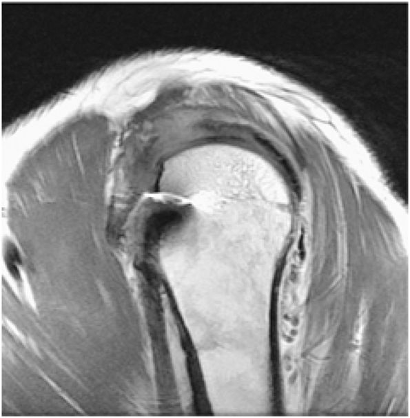 |
|
FIGURE 8.332 ● Management with arthroscopic biceps tenodesis is based on the ability to also repair an associated rotator cuff tear. Either a suture-only or suture anchor-to-bone fixation technique can be used. Anchor-to-bone fixation is used when the rotator interval tissues are deficient. Sagittal PD FSE image.
|
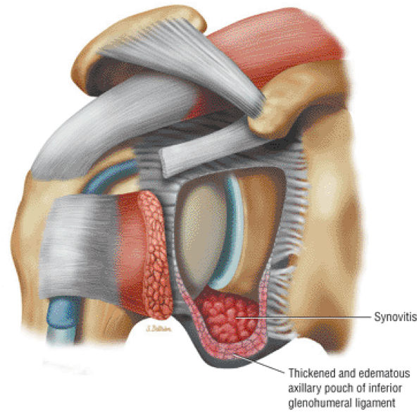 |
|
FIGURE 8.333 ● Adhesive capsulitis or frozen shoulder with thickened inflamed IGHL and synovial thickening within the axillary pouch. Idiopathic adhesive capsulitis is more common than posttraumatic or secondary adhesive capsulitis, which occurs in only 10% of cases.
|
-
Trauma
-
Surgery
-
Degenerative disease
-
Intrinsic rotator cuff and biceps tendinitis/tear
-
Inflammatory disease
-
Metabolic disease (including diabetes mellitus)
-
Synovitis (intermediate signal intensity)
-
Capsular contraction, which may require validation with MR arthrography to appreciate loss of capsular volume and compliancy.
-
Effusion
-
A hyperintense thickened IGHL and intermediate-signal-intensity synovial hypertrophy within the confines of the axillary pouch in symptomatic or active adhesive capsulitis (see Fig. 8.333)
-
A thickened IGHL without hyperintensity on FS PD FSE images (Fig. 8.335) in post-inflammatory changes or scarring of the axillary pouch
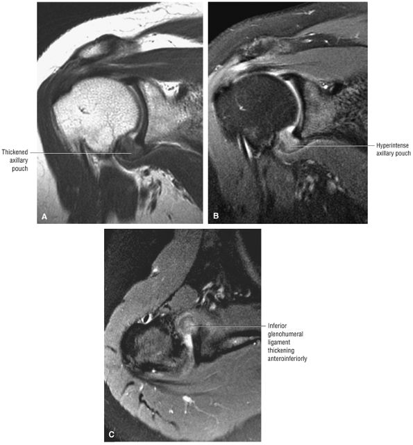 |
|
FIGURE 8.334 ● Coronal PD FSE (A) and FS PD FSE (B) and axial FS PD FSE (C) images of adhesive capsulitis. The thickened, hyperintense axillary pouch produces a soft tissue fullness in the anteroinferior capsule. Primary adhesive capsulitis has a 5:1 female-to-male prevalence. Patients may present with spontaneous insidious pain following a mild or trivial traumatic event including extension or lifting.
|
-
Brisement or distention arthrography leading to capsular rupture
-
Manipulation under anesthesia
-
Arthroscopic capsular release
-
Calcific tendinitis is best visualized as hypointensity on a T2* GRE sequence.
-
The semiliquid state of calcium hydroxyapatite may demonstrate heterogeneous hyperintensity on FS PD FSE images, although hypointensity is still characteristic on T2* GRE images.
-
The supraspinatus and infraspinatus are the most commonly affected tendons.
-
Supraspinatus
-
Infraspinatus
-
Teres minor
-
Subscapularis
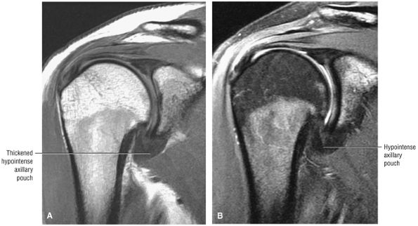 |
|
FIGURE 8.335 ● Coronal PD FSE (A) and FS PD FSE (B) images show the chronic phase of adhesive capsulitis with a thickened IGHL without hyperintensity on the FS PD FSE image (B). MR arthrography is required to demonstrate loss of the inferior capsular recess with scarring.
|
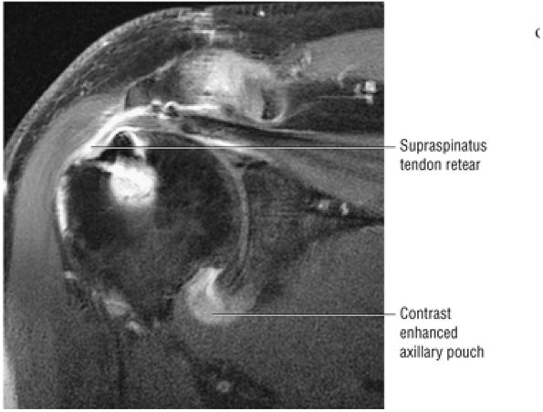 |
|
FIGURE 8.336 ● Intravenous enhancement of the axillary pouch in adhesive capsulitis on a coronal FS T1-weighted MR image. Associated retear of the rotator cuff repair is seen.
|
-
The formation phase
-
The resting phase (no enlargement of deposit)
-
The resorptive phase (inflammation with cells resorbing calcium)
-
The post-calcific phase (reconstruction of tendon integrity)
-
An asymptomatic silent phase (Fig. 8.338), with calcium salts deposited in the critical zone of the tendon
-
A mechanical phase (Fig. 8.339) of enlarging deposits causing intratendinous stress pain associated with intrabursal or subbursal rupture
-
Adhesive periarthritis (Fig. 8.340)
-
Crystalline hydroxyapatite in the tendon
-
Influx of inflammatory cells, especially in the resorptive phase
-
Macrophages and multinuclear giant cells
-
Fibroblasts, in the post-calcific phase
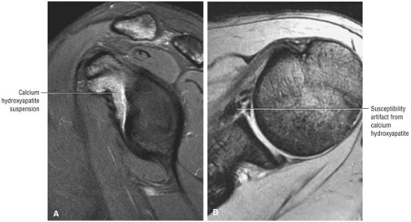 |
|
FIGURE 8.337 ● (A) Sagittal FS PD FSE and (B) axial T2* GRE images of calcific tendinitis subscapularis bursal variant with intermediate-signal-intensity paste-like thickening deep to the subscapularis tendon. GRE images are required to appreciate the susceptibility and hypointensity of the calcium hydroxyapatite crystals.
|
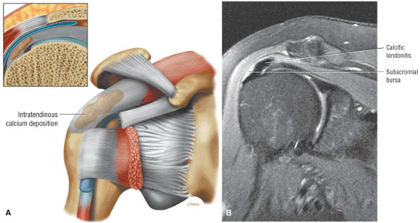 |
|
FIGURE 8.338 ● (A) Coronal 3D color perspective of the silent or subclinical phase of calcium deposition within the substance of the rotator cuff tendons. (B) Transition from the silent phase to the early mechanical phase is characterized by mild elevation of the subacromial bursal floor. Localized hyperintensity of the adjacent subacromial bursa can be seen on this coronal FS PD FSE image.
|
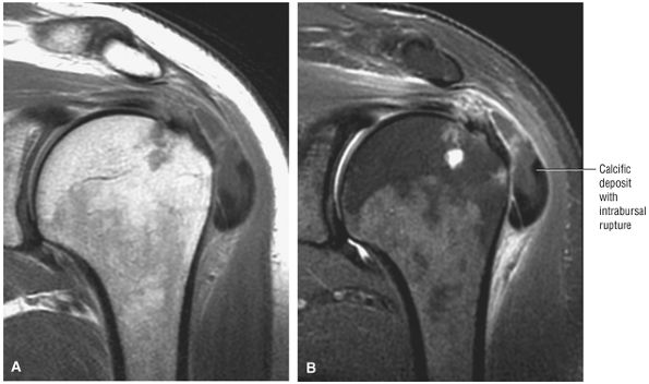 |
|
FIGURE 8.339 ● Coronal PD FSE (A) and FS PD FSE (B) images show the mechanical phase of intrabursal rupture with the bulk of the calcific deposit occupying the subacromial-subdeltoid bursal space. The mechanical phase is characterized by bursal floor elevation, subbursal rupture, or intrabursal rupture.
|
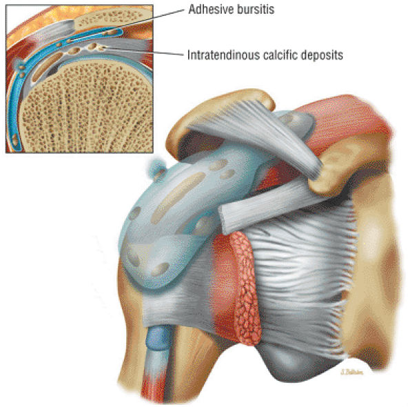 |
|
FIGURE 8.340 ● Adhesive periarthritis demonstrates intratendinous calcific deposits associated with adhesive bursitis and distension of the subacromial bursa. The subacromial subdeltoid bursa may be thickened with areas of intermediate signal intensity. Coronal 3D perspective with 2D coronal section inset in color.
|
-
The bilaminar pectoralis major tendon is formed from the sternocostal and clavicular heads of the pectoralis muscle.
-
Partial musculotendinous pectoralis major tears with combined sternal and clavicular head involvement are the most common presentation.
-
Axial MR images must include the humeral diaphyseal insertion of the lateral lip of the bicipital groove. Coronal oblique images are prescribed parallel to the course of the pectoralis muscle.
of muscle fibers. The most inferior fibers of the sternocostal head insert superiorly and the superior fibers insert inferiorly. The sternocostal head is more susceptible to avulsion than the clavicular head. The pectoralis major is innervated by the medial and lateral pectoral nerves from the medial and lateral cords of the brachial plexus. The pectoralis major functions in adduction and medial rotation of the humerus.
-
Resisted forced abduction and external rotation
-
Forceful contraction with the arm adducted, flexed, and internally rotated
-
Tendon rupture in bench-press weightlifting (muscle failure associated with bench-press lifting is secondary to either overload of the short inferior fibers in the eccentric phase of lifting [sternal head failure] or from a direct blow [sternoclavicular head failure])
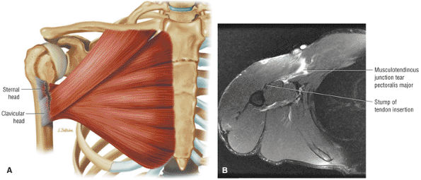 |
|
FIGURE 8.341 ● (A) Coronal color illustration of musculotendinous junction injury involving clavicular and sternal head tendon contributions. (B) Axial FS PD FSE image with hyperintensity and retraction of the pectoralis major in a musculotendinous junction injury with intact remaining stump of tendon insertion.
|
-
Hyperintense edema in the clavicle, sternum, or ribs
-
Increased signal intensity at the humeral insertion in the proximal humeral diaphysis (lateral lip of bicipital groove)
-
Hyperintense edema and hemorrhage within the muscle tear site, perifascial zone, and subcutaneous fat
-
Hematoma with pseudocyst
-
Infection
-
Rupture at the musculotendinous junction
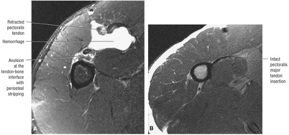 |
|
FIGURE 8.342 ● (A) Axial FS PD FSE image shows complete avulsion of the tendon–bone interface with localized hemorrhage. The pectoralis major muscle may be injured at the tendon–bone interface or the tendon–musculotendinous junction, or intramuscularly. Hematoma and periosteal stripping are associated with primary tendon avulsion. (B) Axial PD FSE image of normal pectoralis major tendon insertion shown for comparison. The hypointense pectoralis major tendon is located directly anterior to the coracobrachialis muscle.
|
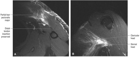 |
|
FIGURE 8.343 ● Partial tear involving both the clavicular and sternal head with preservation of the distal tendon insertion on axial FSE PD (A) and coronal oblique FS PD FSE (B) images. There is greater disruption of clavicular head muscle fibers appreciated on the coronal oblique image of the pectoralis muscle.
|
-
AC separations range from AC ligament sprains to complete disruption of the AC joint capsule and coracoclavicular ligaments.
-
Displacement between the coracoid and clavicle and the position of the distal clavicle relative to the acromial facet are assessed on sagittal and coronal images.
-
Associated fractures may occur in the coracoid, acromion, or clavicle.
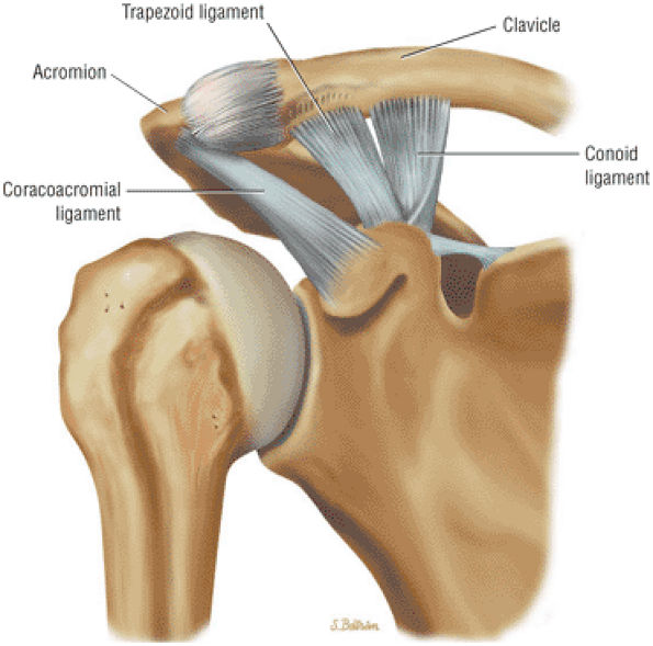 |
|
FIGURE 8.344 ● Anterior view coronal color perspective of the normal trapezoid and conoid ligaments, which function as a single coracoclavicular ligament. The conoid is posterior and medial, whereas the trapezoid is anterior and lateral.
|
-
Type I: AC ligamentous sprain
-
Type II: AC joint disruption with intact coracoclavicular ligaments
-
Type III: AC joint and coracoclavicular ligament disruption. The coracoclavicular interspace is widened 25% to 100% (Fig. 8.345) and the distal clavicle is mobile in both superior to inferior and anteroposterior directions.
-
Type IV: Posterior displacement of the clavicle into or through the trapezius (Fig. 8.346)
-
Type V: Type III separation with greater displacement (100% to 300% compared to the contralateral side) between the coracoid and clavicle (Fig. 8.347)
-
Type VI: Inferior dislocation of the clavicle inferior to the acromion (subacromial) or coracoid (subcoracoid)
ligaments. The relative position of the distal clavicle to the acromion is also assessed. Associated fractures of the coracoid, acromion, midclavicle, and/or distal clavicle with extension into the AC joint are also evaluated. It is important to establish the integrity of the coracoacromial ligament to determine whether allograft reconstruction may be required. Indications for surgical intervention include types IV, V, and VI dislocations. Treatment options for types I and III AC dislocations are more controversial and are often based on activity requirements (i.e., needs of an athlete compared to those of a laborer or someone with a more sedentary lifestyle).
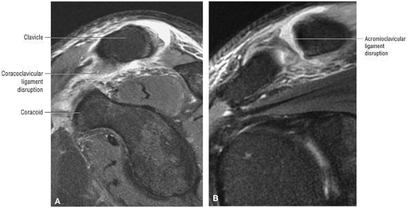 |
|
FIGURE 8.345 ● (A, B) Type III AC separation with complete disruption of both the AC and CC ligaments. The distal clavicle is above the superior border of the acromion. The CC interspace is usually widened by 25% to 100%. The space between the coracoid and clavicle is normally between 1.1 and 1.3 cm. (A) Sagittal FS PD FSE image. (B) Coronal FS PD FSE image.
|
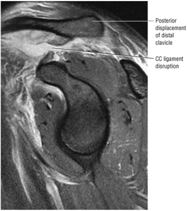 |
|
FIGURE 8.346 ● Type IV AC separation with the distal clavicle displaced posteriorly into the trapezius. There is a fluid-filled gap between the torn and separated CC ligaments and widening of the AC joint space in the coronal plane. Sagittal FS PD FSE image.
|
-
Central and posterior glenoid wear with sclerosis and cartilage loss is typically seen in osteoarthritis.
-
Loose bodies are frequently located in the subscapularis recess.
-
Coronal images demonstrate the medial and inferior projection of humeral head osteophytes. Spurring is also present directed from the inferior pole of the glenoid.
-
Severe glenohumeral osteoarthritis may be associated with reactive subchondral marrow edema.
-
Rheumatoid-related synovial hypertrophy or pannus is intermediate in signal intensity on FS PD FSE images and will enhance with intravenous contrast.
-
Rotator cuff tears are commonly seen in association with rheumatoid arthritis.
-
Rice bodies are hypointense on FS PD FSE images and represent detached fibrotic synovial villi.
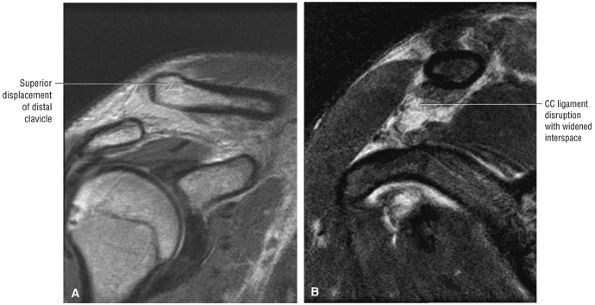 |
|
FIGURE 8.347 ● (A, B) Type V AC separation with complete disruption of the AC and CC ligaments and severe superior displacement of the distal clavicle. The deltoid and trapezius aponeurosis is avulsed from the distal clavicle and the distal clavicle is displaced subcutaneously, with the CC interspace widened 100% to 300%. (A) Coronal PD FSE image. (B) Sagittal PD/T2 FSE image.
|
recurrent dislocation, and rotator cuff arthropathy (see discussion below).
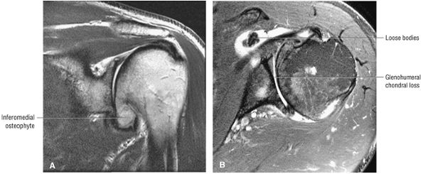 |
|
FIGURE 8.348 ● Coronal T2 FSE (A) and axial FS PD FSE (B) images of osteoarthritis with glenohumeral chondral loss, inferomedial osteophytes, and subscapularis bursa loose bodies.
|
-
Proximal humeral fractures have been grouped into involvement of the anatomic neck, greater tuberosity, lesser tuberosity, and surgical neck.
-
Fracture displacement and angulation requires correlation of coronal and axial images.
-
A chondral SLAP fracture involves the posteromedial superior humeral head.
-
In acute fractures, T2* GRE images may be useful if hyperintense marrow edema obscures fracture site morphology or if a number of segments are involved.
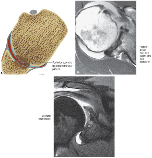 |
|
FIGURE 8.349 ● (A) Axial color section illustrating posterior or eccentric wear pattern of osteoarthritis with loss of posterior glenohumeral joint articular cartilage. Axial PD FSE (B) and coronal FS PD FSE (C) images showing posterior glenoid eccentric wear with subchondral fracture, chondral delamination, and joint space narrowing. MR is used to assess the wear pattern and glenoid bone stock, important in planning the resurfacing of the glenoid.
|
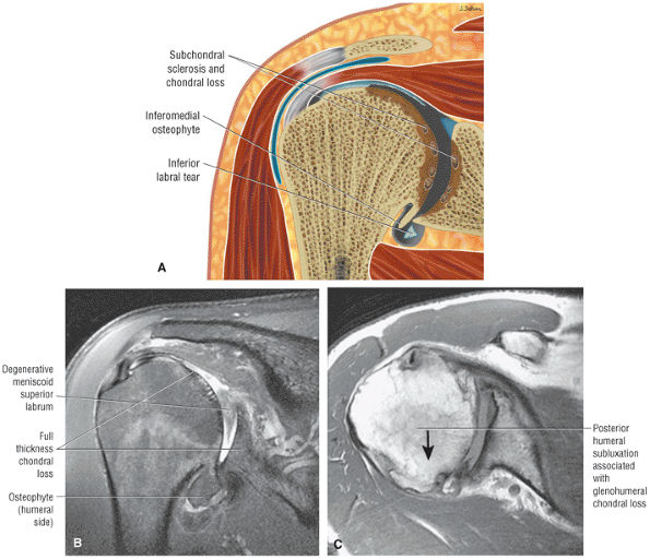 |
|
FIGURE 8.350 ● Advanced changes of osteoarthritis of the glenohumeral joint. Articular cartilage loss with sclerosis and subchondral cystic change is greatest in the area of the humeral head in contact with the glenoid between 60° and 100° of abduction. Characteristic large peripheral osteophytes develop inferiorly and limit rotation by effectively enlarging the diameter of the humeral head. (A) Coronal color section of degenerative osteoarthritis of the glenohumeral joint. (B) Coronal FS PD FSE image with full-thickness glenohumeral articular cartilage loss, inferior osteophytes, and labral tearing shown at the BLC and inferior glenohumeral ligament labral complex. (C) Axial PD FSE with posterior glenoid wear advancing to involve the entire glenohumeral joint. Posterior glenoid wear is associated with an internal rotation contracture and posterior subluxation of the humeral head.
|
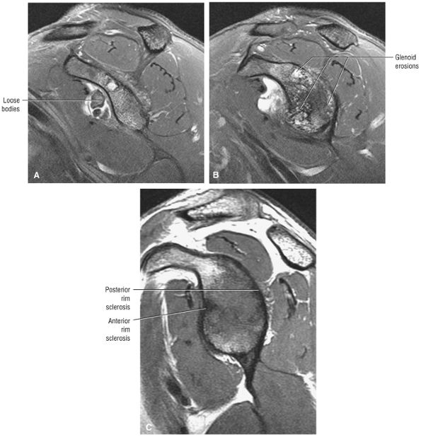 |
|
FIGURE 8.351 ● Loose bodies, glenoid erosions, and soft tissue contractures all limit active and passive range of motion in osteoarthritis, although the rotator cuff is usually intact. (A) Sagittal FS PD FSE image with subscapularis bursa loose bodies. (B) Sagittal FS PD FSE image of diffuse glenoid rim erosions of osteoarthritis. (C) Sagittal PD FSE image for comparison with multidirectional instability in a 20-year-old wrestler. In contrast to osteoarthritis, the anterior and posterior rim sclerosis of MDI is shown without chondral wear or subchondral cystic erosion. This instability may eventually be associated with glenohumeral arthritis but should be identified and differentiated at this stage.
|
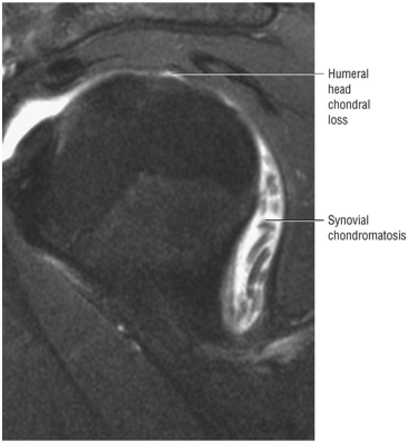 |
|
FIGURE 8.352 ● Secondary chondromatosis associated with full-thickness chondral loss of the humeral head on a sagittal FS PD FSE image.
|
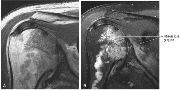 |
|
FIGURE 8.353 ● Atypical manifestation of osteoarthritis with intraosseous ganglion extending into the proximal humeral diaphysis as seen on a coronal PD FSE image (A) and a coronal FS PD FSE image (B).
|
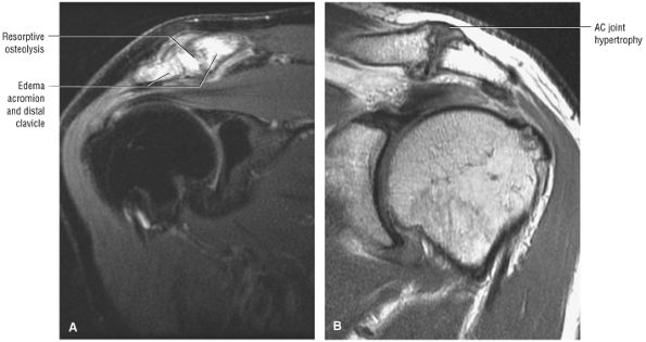 |
|
FIGURE 8.354 ● (A) Coronal FS PD FSE image showing AC joint with hyperintense edema of the distal clavicle and adjacent acromion in a weightlifter. Repetitive microtrauma is associated with posttraumatic arthritis, including osteolysis. The “weightlifter's clavicle” represents subchondral injury with microfractures and resorptive osteolysis. (B) Coronal PD FSE image showing AC joint arthrosis associated with rotator cuff impingement. Characteristic AC joint hypertrophy, greater tuberosity squaring, inferior acromial spurs, and full-thickness rotator cuff tear are shown.
|
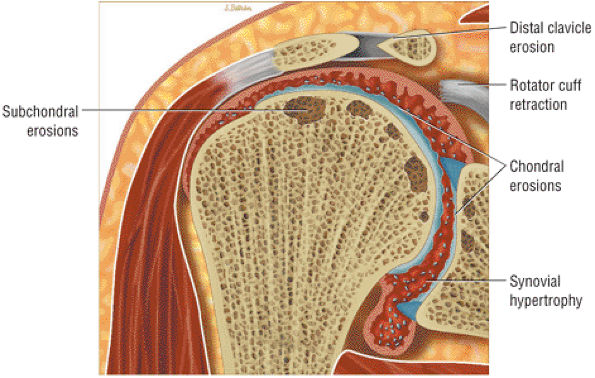 |
|
FIGURE 8.355 ● Rheumatoid arthritis targets the glenohumeral joint but may involve all synovial-lined joints, including the acromioclavicular and sternoclavicular joints. Marginal erosions and subchondral cysts may involve large areas of the humeral head. Glenoid destruction is associated with central or peripheral erosions. Sclerosis and osteophytosis are not common and represent the development of secondary osteoarthritis. Chondral loss, subchondral erosions, and synovial pannus are shown on this color coronal illustration. Erosion with tapering of the distal clavicle is also indicated.
|
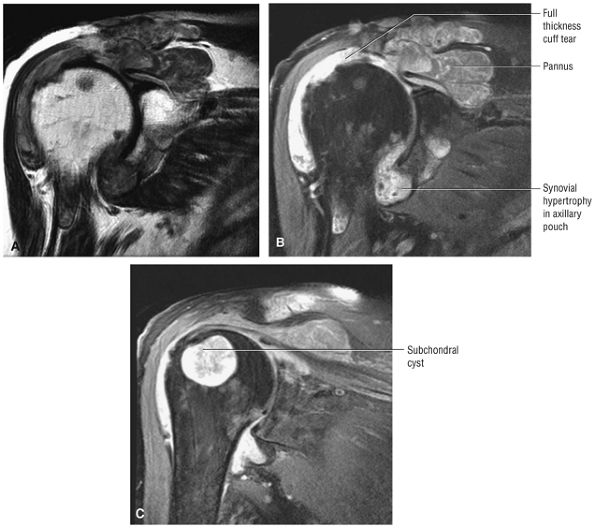 |
|
FIGURE 8.356 ● Coronal PD FSE (A) and FS PD FSE (B, C) images showing rheumatoid arthritis with severe proliferative granulation tissue or pannus destroying articular cartilage and invading subchondral bone of the greater tuberosity. The pannus has destroyed the distal clavicle and has attached to the joint capsule and torn cuff tendons.
|
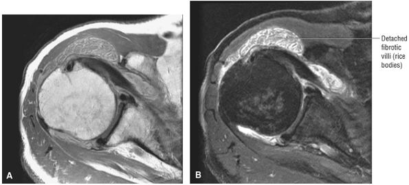 |
|
FIGURE 8.357 ● Intermediate-signal rice bodies or detached fibrotic villi of rheumatoid arthritis shown on axial PD FSE (A) and FS PD FSE (B) images.
|
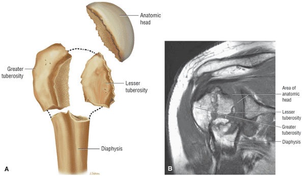 |
|
FIGURE 8.358 ● (A) Division of the proximal humerus into four separate fragments based on anatomic lines of epiphyseal union. These distinct fragments are the greater tuberosity, the lesser tuberosity, the anatomic head, and the diaphysis. (B) Coronal PD FSE image with fracture fragments involving the greater tuberosity anatomic head, shaft, and lesser tuberosity identified.
|
-
Those involving the anatomic neck of the humerus (Fig. 8.359)
-
Those involving the greater tuberosity (Fig. 8.360)
-
Those involving the lesser tuberosity (Fig. 8.361)
-
Those involving the shaft or surgical neck of the humerus (Fig. 8.362)
-
Although the risk of avascular necrosis (AVN) increases with three- and four-part fractures, displacement is not required to cause osseous ischemia.
-
MR findings of AVN may be subchondral or metaphyseal in location.
-
Extended hyperintense marrow edema of the proximal humerus is often associated with the more acute stages of AVN.
-
Sagittal images are helpful in assessing early subchondral collapse with a flattening in the humeral head contour.
-
Steroid use, including post-transplantation therapy
-
Dysbaric disorders
-
Vasculitis
-
Alcoholism
-
Sickle cell disease
-
Hyperuricemia
-
Gaucher disease
-
Pancreatitis
-
Familial hyperlipidemia
-
Lymphoma
-
Stage 1: Asymptomatic; conventional radiographs produce negative results, whereas MR imaging results are positive for alterations in subchondral marrow (Fig. 8.369).
-
Stage 2: Clinically characterized by pain; the humeral head retains its specific shape, although mild depression of the articular cartilage may be present in an area of subchondral bone.
-
Stage 3: Subchondral collapse or fracture with overlying articular cartilage irregularity is seen. No involvement of the glenohumeral joint articular cartilage is found.
-
Stage 4: Incongruity of the glenohumeral joint
-
T1-weighted images in at least one plane provide yellow marrow fat contrast relative to the patchy hypointensity of osseous osteomyelitis.
-
T2* GRE images, although not sensitive for infection, can increase specificity in the diagnosis of osteomyelitis if areas of trabecular hyperintensity are shown. A non-marrow-sensitive sequence that demonstrates hyperintensity in association with joint sepsis is consistent with the spread or extension of osteomyelitis.
-
Intravenous contrast, although not specific for osteomyelitis, is used to enhance soft tissue tracts and abscesses, which may communicate with adjacent osseous erosions.
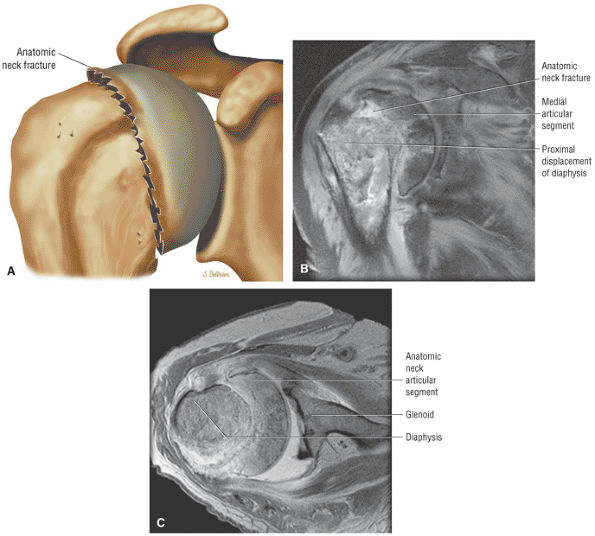 |
|
FIGURE 8.359 ● (A) Fracture of the anatomic neck as the articular segment. (A one-part fracture has no or minimal displacement or angulation. A two-part fracture has one segment displaced. A three-part fracture has two segments displaced with one tuberosity in continuity with the head. A four-part fracture has three segments displaced.) (B) Coronal PD FSE image of a displaced two-part fracture of the anatomic neck with proximal displacement of the diaphysis relative to the medial articular segment. (C) Axial PD FSE image showing the three-fragment sign of the shaft, anatomic neck, and glenoid visualized on a single axial image.
|
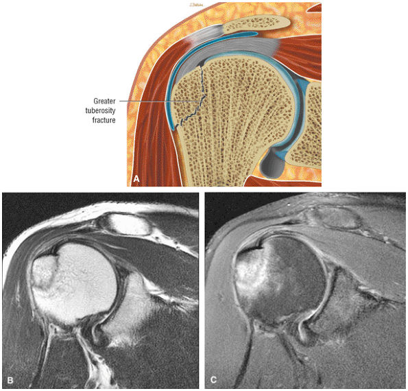 |
|
FIGURE 8.360 ● (A) Nondisplaced greater tuberosity fracture. Fractures of the greater tuberosity are associated with anterior dislocations. A greater tuberosity fracture usually reduces into a acceptable anatomic position but may displace underneath the acromial process or be directed posteriorly by the pull of the rotator cuff muscles. Impacted greater tuberosity fracture without superior displacement on coronal PD FSE (B) and FS PD FSE (C) images.
|
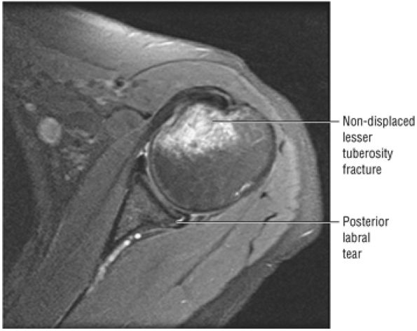 |
|
FIGURE 8.361 ● Axial FS PD FSE image showing a lesser tuberosity fracture associated with a posterior labral tear and dislocation. A fracture of the lesser tuberosity may be pulled anteriorly and medially by the subscapularis muscle.
|
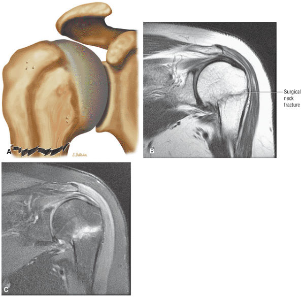 |
|
FIGURE 8.362 ● (A) Surgical neck fracture with no displacement. Surgical neck fracture with minimal angulation on coronal PD FSE (B) and FS PD FSE (C) images. A fall onto the outstretched hand is the most common mechanism for a proximal humerus fracture.
|
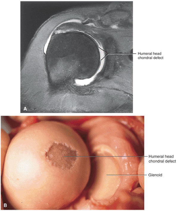 |
|
FIGURE 8.363 ● (A) Coronal FS T1-weighted MR arthrogram of the posteromedial location of a SLAP fracture of the articular surface of the superior humeral head caused by a fall onto an outstretched arm. A chondral divot can be seen in the superior dome of the humeral head. (B) Corresponding gross dissection of the SLAP fracture. (From
Stoller DW. MRI, arthroscopy, and surgical anatomy of the joints. Philadelphia: Lippincott-Raven, 1999
, with permission.) |
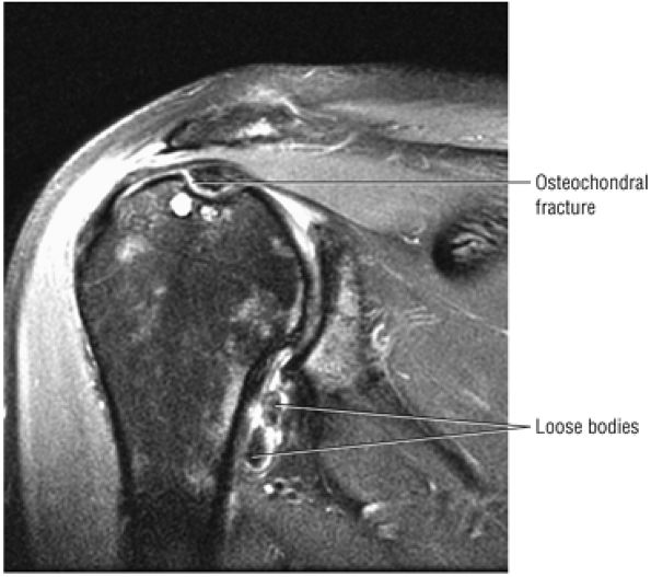 |
|
FIGURE 8.364 ● Focal osteochondral lesion involving the chondral and subchondral bone of the superior humeral head. Loose bodies are demonstrated in the axillary pouch on this coronal FS PD FSE image.
|
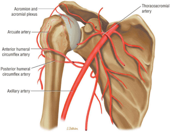 |
|
FIGURE 8.365 ● Coronal color graphic view of the blood supply of the humeral head. The major or primary vascular supply to the humeral head is from the anterior humeral circumflex artery. The arcuate artery, a continuation of the ascending branch of the anterior humeral circumflex, supplies the humeral head, including the greater and lesser tuberosities. A secondary or smaller contribution to the humeral head blood supply is derived from branches of the posterior circumflex artery and the tendinous–osseous anastomoses of the vascular rotator cuff.
|
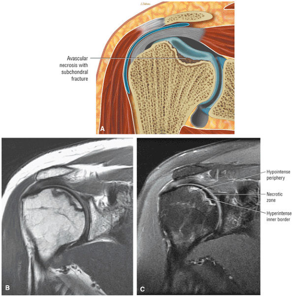 |
|
FIGURE 8.366 ● Localized nontraumatic AVN associated with systemic lupus erythematosus. Lupus patients who are not on glucocorticoids or immunosuppressive drugs are at increased risk for septic arthritis and osteonecrosis. Osteonecrosis occurs in 4% to 15% of lupus patients and affects the humeral head in 80% of cases. (A) Color coronal illustration anterior view of osteonecrosis with subchondral fracture. Corresponding coronal PD FSE (B) and FS PD FSE (C) images demonstrate AVN prior to subchondral collapse. The double line sign of osteonecrosis consists of a hyperintense inner border and a hypointense outer margin on the FS PD FSE image (C).
|
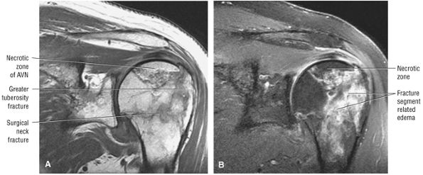 |
|
FIGURE 8.367 ● Nondisplaced surgical neck and greater tuberosity fracture with humeral head AVN on coronal PD FSE (A) and FS PD FSE (B) images.
|
-
Hematogenous
-
Secondary to contiguous spread from osteomyelitis
-
Secondary to trauma, surgery, or intra-articular injection (Fig. 8.371)
of a failed joint replacement with a chronically torn and atrophied rotator cuff. In the reverse shoulder replacement, the glenoid socket is replaced with an artificial ball and the humeral head is replaced by a socket implant. This configuration thus reverses the normal relationship of the humeral head to the glenoid.
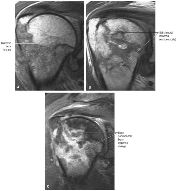 |
|
FIGURE 8.368 ● Development of humeral head AVN 3 months after anatomic neck fracture with involvement of the greater tuberosity. This pattern of deep subchondral ischemia demonstrates morphologic features of a bone infarct. (A) Coronal PD FSE at initial fracture. (B) Coronal PD FSE 3 months after fracture. (C) Coronal FS PD FSE 3 months after fracture.
|
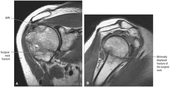 |
|
FIGURE 8.369 ● A minimally (<1 cm) displaced surgical neck fracture with AVN of the humeral head on coronal PD FSE (A) and sagittal PD FSE (B) images.
|
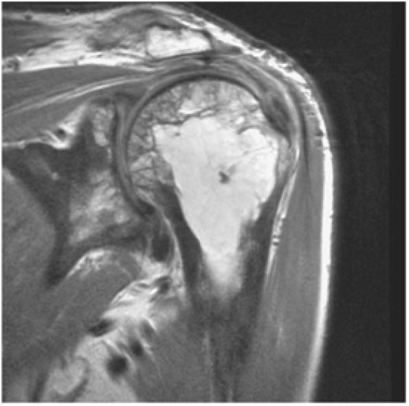 |
|
FIGURE 8.370 ● Coronal PD FSE image showing increased osseous resorption and bone formation, characteristic changes of Paget—s disease. The osseous appearance may mimic fracture and metastatic carcinoma. The three phases of Paget—s disease are lytic, mixed lytic and blastic, and blastic phases. Pagetoid marrow contains new bone formation and fibrovascular tissue and is at an increased risk for fracture.
|
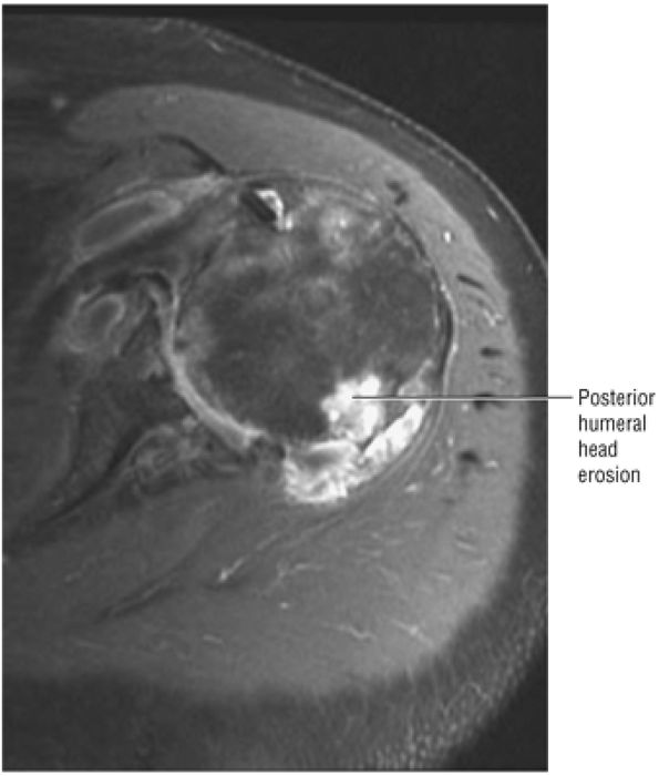 |
|
FIGURE 8.371 ● Axial FS PD FSE image of osteomyelitis secondary to injection of steroids with focal posterior humeral head erosion and soft tissue hyperintense complex fluid collection.
|
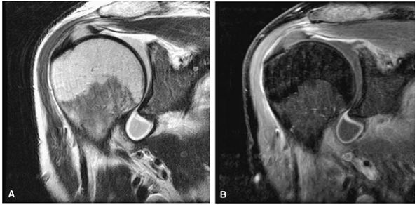 |
|
FIGURE 8.372 ● Septic shoulder with a hyperintense outline of inflammatory fluid within the axillary pouch as seen on coronal PD FSE (A) and FS PD FSE (B) images. There is no osseous involvement at this stage.
|
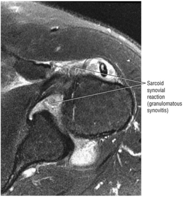 |
|
FIGURE 8.373 ● Sarcoid inflammatory reaction may be mistaken for a septic joint. Inflammatory arthropathy is a common feature of sarcoidosis.
|
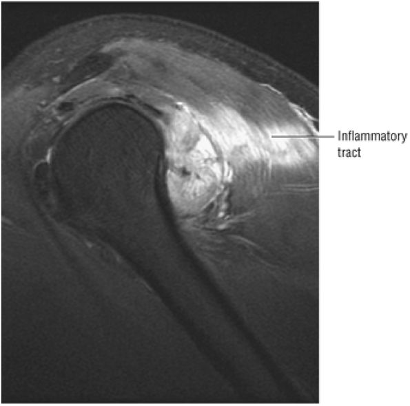 |
|
FIGURE 8.374 ● Sagittal FS PD FSE image of an inflammatory tract with myositis that developed as a reaction to a flu inoculation.
|
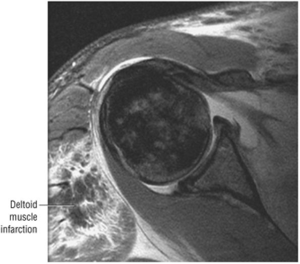 |
|
FIGURE 8.375 ● Rarely, infectious myositis is complicated by a muscle infarction. Fibrotic myopathy, which usually involves the deltoid and quadriceps, may produce similar muscle hypointensity as a complication of direct intramuscular injection of drugs, as seen on this axial FS PD FSE image.
|
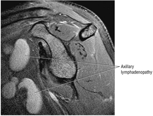 |
|
FIGURE 8.376 ● Sagittal FS PD FSE image showing enlarged axillary lymph nodes in chronic lymphocytic leukemia.
|
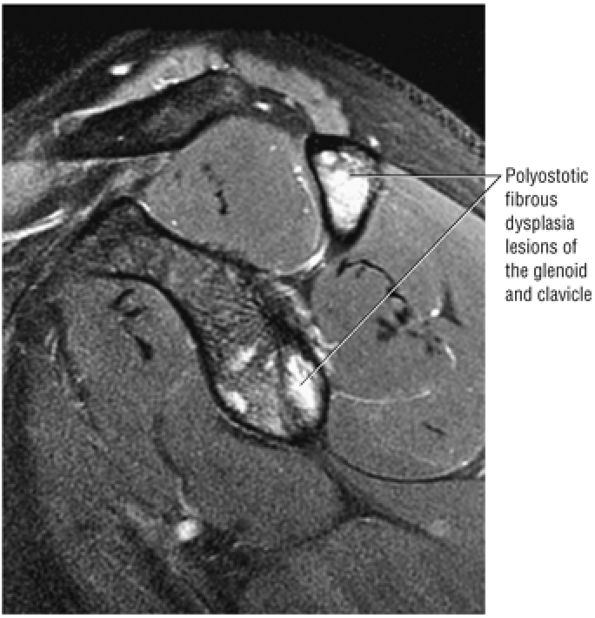 |
|
FIGURE 8.377 ● Osseous involvement of the glenoid and clavicle in polyostotic fibrous dysplasia, which may be mistaken for infection or metastatic disease, is seen on this sagittal FS PD FSE image.
|
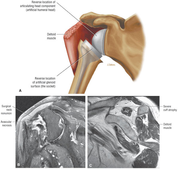 |
|
FIGURE 8.378 ● (A) Reverse shoulder replacement optimizes the force of the deltoid (by increasing the lever arm) and stabilizes the glenohumeral articulation by moving the center of rotation of the glenohumeral joint medially and inferiorly. This provides an increased mechanical advantage for raising the arm overhead. Non-union of a surgical neck fracture complicated by humeral head AVN on a coronal FS PD image (B) and a corresponding sagittal PD FSE image (C). The sagittal plane image demonstrates severe supraspinatus atrophy with a rotator cuff deficient shoulder, fracture non-union, and humeral head AVN. Reverse prostheses may be used to direct forces through the glenosphere, converting centrifugal or outward forces into centripetal or inward forces.
|