
II – FRACTURES, DISLOCATIONS, NONUNIONS, AND MALUNIONS > Malunions
and Nonunions > CHAPTER 26 – PRINCIPLES OF TREATMENT OF NONUNIONS
AND MALUNIONS
edition, portions of this chapter were written by Howard Rosen, Sir
Dennis Paterson, Carl T. Brighton, and Peter M. Stevens. Their
contributions are appreciated.
not heal within the expected time after treatment. This very general
definition reflects the multiple factors involved in determining when a
fracture has become a delayed union. For example, a stable fracture of
the distal radius in a healthy 33-year-old patient treated in a
short-arm cast would be expected to heal by 6 weeks; if it does not
heal by 12 weeks, it might be regarded as a delayed union. On the other
hand, a displaced subcapital fracture of the femoral neck in a 70-year
old treated with percutaneous cannulated screw fixation would be
expected to heal in 6 months; it would be regarded as a delayed union
if it had not healed by 6 months. Factors influencing the rate of union
are the same as those that can lead to nonunion and are listed in Table 26.1.
 |
|
Table 26.1. Causes of Nonunion
|
tenderness, and motion at the fracture site. Radiographic hallmarks of
delayed union are persistence of the fracture line, hypertrophic callus
with a persistent fracture line, and minimal or no callus production (60,84) (Fig. 26.1).
If internal fixation is present, fracture lines may be persistent or
show evidence of resorption; there may be evidence of failure of
fixation in the form of halos around screws, or there may be evidence
of implant breakage.
 |
|
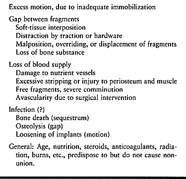
Figure 26.1.
Microangiogram of a 6-week-old canine radius fracture, showing delayed union. Note the tremendous increase in vascularity and the inability of the capillaries to penetrate the fibrocartilage of this hypertrophic delayed union. (From Rhinelander FW. The Normal Microcirculation of Diaphyseal Cortex and Its Response to Fracture. J Bone Joint Surg Am 1968;50:784.) |
different factors that must be considered. In general, the absence of
any clinical or radiographic evidence of progression of fracture
healing for 2–3 months after the expected time period for healing
constitutes a nonunion. Be cautious in applying this definition, as
some progression toward union may occur that is not detectable by the
usual means. This is evidenced by the fact that an occasional
“nonunion” treated nonoperatively in a weight-bearing cast will
eventually go on to union. In diaphyseal fractures of major long bones
in adults, the diagnosis of nonunion should not be made until 6 months
after the fracture (57,60).
The clinical signs are discussed in the next section. Radiographically,
a nonunion shows no evidence of bone bridging the fracture site.
Finally, the diagnosis of nonunion infers that the fracture will not go
on to union without some type of therapeutic intervention, either
nonoperative or surgical.
only minimally, is interrupted, or does not result in the formation of
bridging bone; instead it produces only fi-brous
tissue
or cartilage, which is interposed in the fracture site in the absence
of bony callus bridging between the two major fracture fragments (Fig. 26.2) (89).
Unless obscured by overlying hypertrophic callus, a radiolucent line
representing the zone of fibrous and/or cartilaginous tissue is evident
on plain radiographs (Fig. 26.3).
 |
|
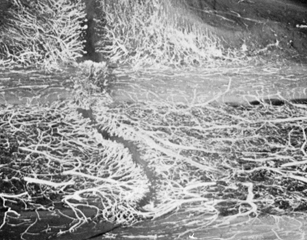
Figure 26.2.
Roentgenographic appearance and histology of a 20-week experimental canine hypertrophic pseudarthrosis. A radiolucent area is intensely stained, unmineralized fibrocartilage and weakly stained fibrous tissue in the gap. Note cleftlike fissure of a neoarthrosis and sclerotic bone ends. (From Schenk RK. Histology of Fracture Repair and Nonunion. Bulletin of the Swiss Association for Study of Internal Fixation, Bern, Oct. 1978.) |
 |
|
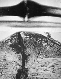
Figure 26.3. A:
Hypertrophic vascular nonunion 1.5 years after inadequate intramedullary nailing. Motion continues at the fracture with weight bearing. Bending, torsional, and shear stresses are not stabilized by the nail. B: Atrophic avascular nonunion 1 year after inadequate intramedullary nailing. Mechanical instability and avascularity have caused this nonunion. |
cartilage in the presence of significant motion, often a cleft will
develop in the cartilage. The surrounding fibrous tissue forms a
pseudocapsule; with sealing of the bone ends and remodeling, a false
joint, or pseudarthrosis, is formed. A serum transudate is usually
found in these pseudarthroses, which is evident upon incision through
the fibrous capsule into the pseudarthrosis as normal-appearing “joint
fluid” exudes forth. Atrophic and oligotrophic nonunions (see the classification,
below) are characterized by minimal or no formation of cartilage, a
predominance of fibrous tissue formation, and what appears to be an
aggressive osteoclastically mediated resorption of the bone ends,
resulting in a pencil-like configuration of the ends of the major bone
fragments. In part, this picture may be caused by actual mechanical
erosion of the bone ends resulting from weight bearing or excessive
motion. This picture is more common in the presence of pathologic
nonunions, such as in congenital nonunions associated with
neurofibromatosis (see Chapter 174, Chapter 178, and Chapter 180).
The most common cause of nonunion in wild animals, and in humans
despite modern treatment, is excessive motion at the fracture site.
Bone modeling and remodeling and fracture repair are mediated by cell
behavior in response to many different signals, including mechanical
ones. Molecular biological and cellular factors play a key role, but
motion at the fracture site is the primary cause of nonunion: It
results in cell and matrix disruption that prevents bridging of the
fracture site by calcified or ossified tissue. A particularly unique
mechanical situation is created by the rigid internal fixation of
long-bone fractures with plates: The close apposition of the fracture
fragments in the presence of micromotion introduces high strain rates
across the fracture site that may play a role in nonunion (75).
When the classical Arbeitsgemeinschaft für Osteosynthesefragen (AO)
methods of rigid internal fixation are employed, particular care must
be taken to eliminate micromotion between the
fracture fragments through interfragmentary compression and fixation (60).
blood supply to the bone ends at the fracture site or in the
surrounding soft-tissue envelope. High-energy trauma resulting in
severely displaced fractures, particularly if they are open, can
devascularize the bone ends by severe stripping of soft tissues from
the bone, as well as by interruption of the medullary and
extramedullary blood supply. Certain fractures have a higher incidence
of nonunion due to anatomic factors in the vascular supply to bone that
result in loss of blood supply to one or more of the major bone
fragments. Typical examples are displaced subcapital fractures of the
femoral neck, which result in avascular necrosis of the femoral head
and nonunion of the femoral neck; fractures at the waist of the carpal
scaphoid, which result in avascularity of the proximal pole and
nonunion; and fractures of the neck of the talus, which can result in
loss of blood supply to the body of the talus, particularly if
associated with a subtalar or ankle dislocation.
injured patient, involves the routine use of various methods of
internal fixation for long-bone fractures, particularly in the lower
extremity, and in periarticular and displaced intraarticular fractures.
Inappropriate surgical techniques can lead to further devascularization
of the bone through excessive soft-tissue stripping; obliteration of
the intramedullary blood supply through reaming or the insertion of
implants; necrosis of bone by overheating with power instruments;
surgical interruption of major vessels that are critical sources of
blood flow to bone, such as the medial circumflex femoral artery at the
hip; and, finally, excessive coverage of bone surfaces with metallic
implants, such as large double plates and intramedullary nail and plate
combinations, which precludes revascularization of the bone. For the
most part, these factors are under the control of the surgeon.
Uncontrolled infection, however, causes nonunion, predominantly because
purulent material dissects under pressure within the intramedullary
canal and along the subperiosteal surfaces of bone, resulting in bone
necrosis. The inflammatory response to the infectious process may also
lead to an excessive remodeling response causing osteolysis, which
further slows the rate of union.
major gap in the fracture site, which precludes bridging by healing
callus. Such gaps are most commonly caused by interposition of soft
tissue, in particular muscle, as well as periosteum, tendons, and
nerves. Gaps can also result from the wide displacement of intercalary
fragments in closed fractures and actual loss of bone substance in open
fractures, particularly from close-range or high-velocity gunshot
wounds.
health play a role in fracture union but are not causal factors per se.
Evidence suggests that excessive intake of nicotine through tobacco
consumption may, by its effect on the microvasculature, play a
significant factor in predisposing to delayed union or nonunion. Other
important factors include a fracture in a previously irradiated
extremity, severe malnutrition, and the use of medications such as
anticoagulants, steroids, and anticonvulsants. Age is a factor insofar
as it leads to rapid and nearly always successful union in patients
with open physeal lines and in particular in newborns where fractures
can heal in a matter of days.
include the time elapsed since the original fracture or previous
treatment, whether the nonunion is mobile or stable, and whether it is
a synovial pseudarthrosis. The site, whether diaphyseal or metaphyseal,
and the coexistence of shortening and angular or rotational deformity
greatly influence treatment decisions, as does the presence of intact
or broken internal fixation. It is, of course, critically important to
know whether the nonunion is infected.
 |
|
Table 26.2. Factors Involved in Nonunionsa
|
indicator of its blood supply and potential for union, which is
reflected in the Weber-Cech classification (101).
This classification, proposed by Weber and Cech in 1976, is still the
most useful system, although the presence of internal fixation, in
particular intramedullary nails, makes it more difficult to use. They
classified nonunions into two major groups based on whether the bone
ends at the fracture site are vital—that is, whether they have a good
blood supply. They examined plain radiographs to determine the amount
of callus formation and correlated this with radioisotope studies to
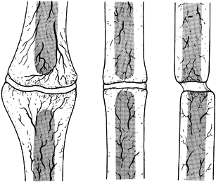
demonstrate the degree of blood supply (Fig. 26.4 and Fig. 26.5). Figure 26.4
shows vital nonunions, which have a good blood supply to both bone
fragments and demonstrate various degrees of callus formation. Figure 26.4A
is a hypertrophic, or elephant’s foot, nonunion, which is usually
caused by mechanical instability. Increasing the mechanical stability
of the fracture site will often permit these to heal. In addition, they
are usually responsive to electrical stimulation. It is important,
however, to differentiate hypertrophic nonunions from true synovial
pseudarthroses. Plain tomography or computed tomography (CT) scans with
sagittal or frontal plane reconstruction will often show a cyst in the
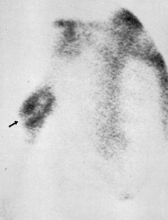
center of the hypertrophic nonunion. An excellent test is a technetium
bone scan, which will show increased uptake throughout the fracture
site, but the center will be cold, as seen in the pseudarthrosis of a
mid-shaft humerus fracture (Fig. 26.6). The other two types of vascular nonunions are the horse’s hoof (Fig. 26.4B) and oligotrophic nonunions (Fig. 26.4C).
These nonunions form less bone, in part because of their lack of
vitality, but this is also influenced by the bone they occur in and
their location in the bone. The oligotrophic nonunion can be difficult
to differentiate from the atrophic nonunion. This differentiation is
important as the former has a much better prognosis as a result of its
reasonably good blood supply.
 |
|
Figure 26.4.
Weber and Cech’s classification of pseudarthrosis. These are the vascularized, or vital, nonunions, which have the biological potential to heal. A: Elephant’s foot hypertrophy. B: Horse’s hoof. C: Oligotrophic (often mistaken for atrophy). (From Weber BG, Cech O. Pseudarthrosis. Bern: Hans Huber, 1976.) |
 |
|
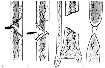
Figure 26.5.
Weber and Cech’s classification of pseudarthrosis. These are the dysvascular, or nonvital, nonunions, in which lack of blood supply, a gap, or another factor limits their ability to heal without biological intervention. A: Dystrophic (torsion wedge with butterfly). B: Necrotic (comminuted fragments). C: Defect (gap). D: Atrophic. (From Weber BG, Cech O. Pseudarthrosis. Bern: Hans Huber, 1976.) |
 |
|
Figure 26.6. Technetium-99m bone scan of a synovial pseudarthrosis of the right humerus. Note cold cleft (arrow) between hot ends. (From Esterhai JL, Brighton CT, Heppenstall RB, et al. Detection of Synovial Pseudarthrosis by 99mTc Scintigraphy. Clin Orthop 1981;161:15.)
|
characterized two nonunions occurring in comminuted diaphyseal
fractures as dystrophic or torsion wedge nonunions with a butterfly
fragment (Fig. 26.5A), and necrotic (Fig. 26.5B)
due to comminuted fragments. In both, there is a devascularized
butterfly fragment, which in the first instance heals to one side of
the fracture and then is partially revascularized. The opposite side
then has a vascularized main fragment abutting a necrotic surface on a
comminuted fragment. The intervening gap is usually filled with fibrous
tissue. In the necrotic nonunion, the healing process fails on both
sides of the comminuted fragment, which produces a devitalized gap.
Both of these nonunions require efforts to induce revascularization of
the devascularized areas, as well as good mechanical stability for
revascularization, and bone grafting to bridge the fracture site.
is caused by loss of bone from the fracture site. In children with open
physes and in some adolescents who are just nearing the end of growth,
large gaps may bridge through periosteal new bone formation. In adults,
however, even gaps 5 mm or less may lead to nonunion, particularly in
the presence of intramedullary nails. To achieve union, gaps must be
filled with bone or bone apposition achieved. Alternatives include
Ilizarov segment transport, direct autologous bone grafting,
allografts, or osteoconductive materials such as corraline
hydroxyapatite, usually combined with a bone-inductive medium such as
bone marrow, stem cells, or bone-inductive proteins.
is particularly difficult to treat because not only does it have a poor
blood supply but a gap is often present. Bone quality may be poor, and
it would appear that there is an active osteoclastically mediated
resorption process, which in some cases is related to an underlying
systemic disorder such as neurofibromatosis. This is the most common
type of congenital nonunion. Dysplastic tissues in the nonunion site
preclude successful long-term formation of bone capable of withstanding
mechanical stress.
prior infection is important, but if the nonunion site shows no local
signs of infection and there has been no active drainage for 6 months
or more (particularly if the previous infection was caused by an
antibiotic-sensitive organism that was successfully eradicated), then
operative intervention can usually proceed. Nonunions with active signs
of infection, however, usually require eradication of the infection
first, with thorough irrigation and debridement, removal of all
devitalized bone, good stability (usually with an external fixator),
and achievement of good-quality, full-thickness soft-tissue coverage.
It is possible to achieve union in the presence of active infection,
but usually it must be eradicated before proceeding with treatment (54).
to achieve solid union of the fracture site, one that will endure and
allow the patient to regain a good level of function. The latter
requires that the limb be left with little or no shortening or
malalignment, and that sufficient joint range of motion, muscle
strength, and neurovascular function be restored that the limb is
useful to the patient. If these objectives are reached, but the patient
continues to have chronic disabling pain, then treatment may have been
fruitless. The primary source of pain in most cases, however, is the
nonunion itself. Healing of the nonunion usually resolves any pain
problems. Reflex sympathetic dystrophy may be a problem in some
patients, particularly if there is an associated neurologic injury, and
especially one involving the brachial or lumbosacral plexus.
can lead to permanent long-term disability in the limb resulting from
muscle atrophy and joint stiffness. If this interferes with the
patient’s return to work and resumption of a normal lifestyle,
significant socioeconomic consequences can occur. This must be taken
into account when proposing treatment for nonunions. Listen carefully
to the wishes and needs of each patient, and understand his treatment
objectives. For example, the best solution for a sedentary individual
with a longstanding, infected nonunion of the tibia with shortening and
deformity and poor function of the foot might be a below-the-knee
amputation, if a good-quality, satisfactory stump can be obtained.
characterize the nature of the original injury and the initial
treatment, as well as all subsequent efforts to repair the nonunion,
including the outcomes of these procedures, and complications.
Particularly important is to establish whether infection has occurred
at any time. Rule out any
potential
systemic aggravating factors that could possibly be treated, and review
habits—in particular, tobacco use. There is substantial evidence that
tobacco interferes with fracture healing and may predispose to
nonunion, so it is prudent to try to persuade smokers with nonunions to
stop smoking. Social history is important, as many operative procedures
require a responsible, cooperative patient who will follow instructions
and engage vigorously in a rehabilitation program.
pain in the fracture site, which is often severe and aggravated by
motion or weight bearing. Ask patients whether they feel motion in the
fracture site, as this may be an important clue. The direction in which
they feel that motion or the mechanism of producing it may also be
helpful.
review of systems, to be certain that the patient can handle the major
surgery often required for nonunions. Evaluate the other components of
the musculoskeletal system to discover other disorders that must be
treated prior to, or concomitantly with, the nonunion to obtain a
successful outcome.
nonunion is motion in the fracture site, occasionally accompanied by
crepitus. Some nonunions are grossly flail, but with internal fixation
in place the detection of motion may be subtle. It is important to look
for just a jiggle of motion in the fracture, which may occur in only
one plane. This requires careful, meticulous, delicate examination with
the fingertips, trying to elicit motion in all planes. If elicited,
this is diagnostic regardless of the radiographic appearance. Extremely
stable fibrous nonunions, and some nonunions in the presence of
internal fixation, may have no motion in the fracture site.
motion, muscle strength, and neurovascular status. Accurately document
shortening. This information is essential to planning an operative
approach that will address all problems and provide the maximum
opportunity for returning function to the limb.
lateral planes, including the joints above and below the fracture site,
are the minimum required. Oblique views are useful for detecting
nonunions that are not in the plane of AP and lateral radiographs (Fig. 26.7). The key to diagnosis on plain films is placing the nonunion in line with the
central beam of the radiograph. This often requires examination under
fluoroscopy, rotating the limb until the fracture site is clearly seen
and then taking a plain film. Tomograms are less useful today because
of the x-ray scatter produced by often-present implants. CT scans with
reconstruction in various planes are very useful, particularly for
fractures in metaphyseal and juxtaarticular areas. I do not use
magnetic resonance imaging (MRI) often in the evaluation of nonunions,
but it is occasionally useful in intraarticular nonunions. Use
technetium bone scans to rule out synovial pseudarthrosis in
hypertrophic nonunions for which you are contemplating treatment with
either electrical stimulation or closed intramedullary nailing (25).
The former is not useful in the presence of synovial pseudarthrosis,
and the latter may cause you to open the fracture and perform a bone
graft in addition to placing the intramedullary nail. I rarely use
other types of scintigraphy to rule out infected nonunions, as this
does not change my surgical approach in the vast majority of cases.
 |
|
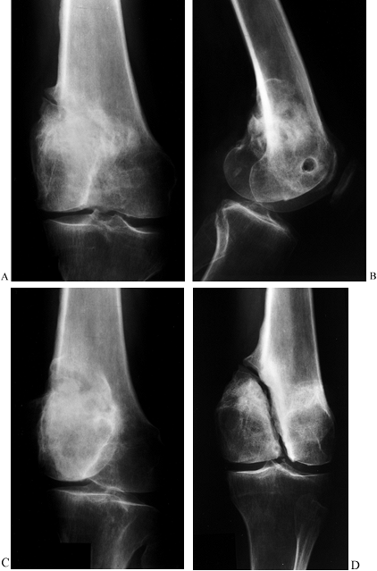
Figure 26.7.
Nonunion of the lateral condyle of the femur. This series of radiographs shows how difficult it is to detect some nonunions, and it demonstrates the importance of having the central beam of the x-ray exactly in line with the axis of the nonunion. A: AP view suggests the presence of a problem because there is partial unhealed fracture in the epicondylar area. Nonunion cannot be seen. B: Lateral view demonstrates apparent union. C: Oblique view likewise appears to show union of the condyle. D: Opposite oblique view shows clearly a well-established, stable fibrous nonunion of the medial condyle. |
immobilization alone in the treatment of nonunions, although a
functional, weight-bearing cast or brace may be useful for a delayed
union of a closed tibial shaft fracture (88).
Simple, continued application of a well-fitted cast or brace combined
with functional weight bearing in the absence of a prematurely healed
fibula, which is preventing compression of the fracture site, may
suffice. An oblique osteotomy of the fibula may be useful in some
circumstances to allow the fracture to compress with weight bearing.
that electricity can induce or stimulate new bone formation. He
observed that 1 microampere (µA) of constant direct current applied to
a rabbit’s femur by Vitallium needle electrodes inserted through the
cortex into the medullary canal produced new bone formation,
particularly in the vicinity of the negative electrode, or cathode.
Since that first report, many investigators have demonstrated that
electricity in its various forms—direct current, inductive coupling or
pulsed electromagnetic fields (PEMFs), and capacitive coupling—can
induce new bone formation using the proper electrical parameters (2,4,7,13,28,29,32,48,55,63,94).
In tissue and bone cells, the initial response to electricity is
increased bone cell proliferation and no change in or decreased matrix
production and alkaline phosphatase activity (13,20,27,47,61,62,65,82,93). Later, matrix production
increases and matrix calcification is stimulated or increased (18,27,60).
osteogenesis is not completely understood. Intracellular calcium and
cyclic adenosine monophosphate (cAMP) have been shown to increase in
some studies, but the results are neither significant nor consistent
enough for intracellular calcium or cAMP to be considered the primary
intracellular messenger of an extracellular electrical signal (12).
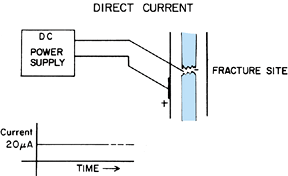
formation is different for each of the three methods. The direct
current method is the most complex, possessing electric, chemical, and
mechanical effects, all of which may stimulate new bone formation. A
constant direct current of 20 µA is applied to the electrodes, with the
cathode located in the bone site and the anode located in the adjacent
soft tissue or on the surface of the skin (Fig. 26.8).
The electric current flowing between the electrodes probably is the
predominant stimulus of the new bone formation. However, a chemical
reaction also occurs at the electrodes, in which molecular oxygen is
consumed and hydroxyl ions are produced, given the proper parameters of
current and voltage (9,11):
 |
|
Figure 26.8.
Application of direct current (DC) to the fracture site of a nonunion. The negative electrode or cathode is inserted percutaneously. |
(35–40 mm Hg) and when the pH at the bone–cartilage junction in the
growth plate is alkaline (pH 7.7), which favors calcification (14,15,35).
Mechanical effects from the trauma of inserting the cathode and
postinsertion movement of the cathode may also stimulate osteogenesis
in the direct current method (26).
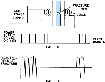
effect and a magnetic effect. A time-varying electric field is applied
to a pair of matched coils placed on opposite sides of the extremity of
interest, or to a single, flexible coil bent to conform to the
extremity. The time-varying electric field applied to the coil(s)
induces a time-varying magnetic field between the coils, and this
induces a secondary time-varying electric field in the tissues,
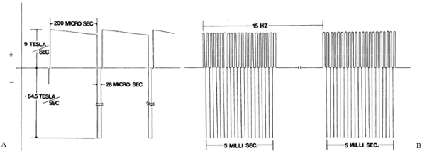
including bone, placed between the coils (Fig. 26.9). The configuration of the PEMF used for nonunions is shown in Fig. 26.10.
 |
|
Figure 26.9. Application of inductive coupling or pulsed electromagnetic fields to the fracture site of a nonunion.
|
 |
|
Figure 26.10. The inductively coupled signal used for treating a nonunion. A: Dimensions of a single pulse. B: Dimensions of a pulse burst.
|
effect; the magnetic field associated with capacitive coupling is
negligible. A time-varying electric field is applied to a pair of
electrodes placed on the surface of the skin on opposite sides of the
injured extremity. The time-varying electric field applied to the
electrodes produces a time-varying electric field in the tissues,
including bone, between the electrodes (Fig. 26.11).
The signal used in treating nonunions is a symmetrical sine wave with a
peak-to-peak amplitude of 5 V and a frequency of 60 kHz. This produces
in the fracture callus an average electric field of 80 mV/cm, with a
range of 20 to 150 mV/cm, depending on the size of the limb and amount
of fat in the extremity. The corresponding values for the current
densities in the callus average 160 µA/cm2, with a range of 40 to 300 µA/cm2.
These values for the electric field and current density produced in the
fracture callus with capacitive coupling are probably similar to those
generated by inductive coupling.
 |
|
Figure 26.11. Application of capacitive coupling to the fracture site of a nonunion.
|
common is the electric effect, and it is assumed to be the dominant
effect in each of the methods of treating nonunion with electricity.
delayed union or nonunion in which operative intervention is not
absolutely required to obtain adequate reduction and fixation, to
remove a synovial pseudarthrosis, or to fill a large bone defect (e.g.,
a gap at the fracture site that is greater in width than the radius of
the bone at that level). If a delayed union or nonunion is already held
in good position and in alignment from a previous internal fixation, or
if the delayed union or nonunion can be held adequately in good
position and alignment by appropriate cast immobilization, and if there
is no large gap or synovial pseudarthrosis, treatment with noninvasive
electrical stimulation may be indicated.
electrical stimulation is a delayed union in good position,
particularly of the diaphysis of the tibia or femur. Most typically,
these are fractures that occurred in patients with multiple injuries,
or they were open fractures that were treated initially with nonreamed,
locked, intramedullary nail fixation. For that reason, they are in good
position, but the magnitude of the initial injury, combined with the
less stable fixation offered by a small nonreamed nail, leads to
delayed union. If at 12 weeks after injury, there is no evidence of
callus formation and the fracture site is still clearly visible, then
the chances of going on to a nonunion are significant. This could lead
to implant failure, angulation, and the necessity for surgery. At that
time in the treatment, I typically offer my patients the opportunity
for operative intervention, usually in the form of an exchanged,
reamed, locked nailing or noninvasive electrical stimulation if they do
not wish to undergo surgery.
fractures in acceptable alignment, which can be adequately immobilized
in functional casts or braces in patients who have significant
contraindications to surgery, such as coexisting infection,
poor-quality soft tissues, or severe systemic illness.
for treating nonunion include a large gap at the fracture site and
synovial pseudarthrosis (25). Brighton (10) states that a large gap occurs in approximately 5% of all nonunions, and synovial pseudarthrosis in approximately
12%, particularly in the humerus and radius. He defines a large gap as
one that is equal to or larger than the diameter of the cortex at the
site of the nonunion. He cites severe osteoporosis as a relative
contraindication, as it lowers the union rate with electrical
stimulation to 25% or less. He defines osteoporosis as occurring when
the combined thickness of both cortices adjacent to the fracture site
is equal to less than 20% of the diameter of the bone at that level as
measured from plain radiographs. Osteomyelitis in the nonunion site is
not a contraindication, as Brighton (10) reported a 58% union rate in 102 nonunions in the presence of osteomyelitis.
-
Nonunion of the humerus, because of the
high incidence of synovial pseudarthrosis and the difficulties in
achieving adequate immobilization of the fracture -
Nonunion of the diaphysis of the radius
or the ulna, if prolonged immobilization in a long-arm cast will result
in permanent loss of functional motion -
Nonunion of the shaft of the femur,
because of the high incidence of synovial pseudarthrosis and the
difficulties in adequately immobilizing the femur -
Any nonunion with unacceptable deformity that requires surgery for correction
-
Apply a well-molded cast to immobilize the nonunion.
-
Position the flexible coil over the nonunion site so that the entire site is within the “window” of the coil.
-
Confirm the location of the coil with
radiographs and secure it with Velcro straps. Incorporate the coil into
the cast with an additional wrap of casting material if the patient is
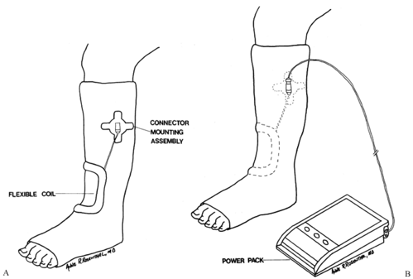
likely to be noncompliant (Fig. 26.12).![]() Figure 26.12. Inductive coupling. A: The connector mounting assembly is positioned near the coil. (Newer models do not require this.) B: The flexible coil and mounting assembly can be incorporated into the cast.
Figure 26.12. Inductive coupling. A: The connector mounting assembly is positioned near the coil. (Newer models do not require this.) B: The flexible coil and mounting assembly can be incorporated into the cast. -
Connect the cable from the coil to the control unit, which can be worn on a belt or carried with an adjustable shoulder strap.
-
Ideally, treat for 10 hours daily. The minimum use per day is 3 hours, but fracture healing will be slower.
-
Encourage full function of the limb
within the limits of the cast, including full weight bearing, unless
motion of more than 5° of angulation will be induced at the fracture
site. -
Examine and x-ray the fracture at 6-week
intervals. If at 12 weeks the fracture is not yet healed but is showing
evidence of progressive healing, continue treatment until healed. If at
12 weeks or later there is no evidence of progress toward healing, then
change treatments. If a bone graft is done, consider combining it with
an implantable stimulator.
-
Apply an appropriate plaster or fiberglass cast to immobilize the nonunion. At the level of the nonunion site, cut two 13/4-inch-square
windows in the cast opposite each other with a cast saw. Place the
windows 180° ± 20° to each other at the level of the nonunion, ±4.5 cm.
Exact alignment of the windows on radiographs is necessary. -
Cut out the padding and stockinet under
the windows. Peel the backing liner off each electrode, and place them
on the skin centrally, one in each of the windows. Depending on the
thickness of the cast, place an appropriate spacer over one or both of
the electrodes to fill the gap in the cast to prevent window edema. To
prevent a pressure sore, do not extend the spacer above the surface of
the cast (Fig. 26.13A).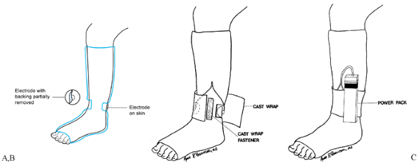 Figure 26.13. Capacitative coupling. A:
One self-adhering, flexible electrode is in place on the skin in one
window, and the backing is partially removed from another electrode
before its placement on the skin through the second window. B:
After the electrodes are in place and connected to the appropriate
leads, a cast wrap is placed around the cast and secured over a
self-adherent fastener strip. C: The leads extend from the electrodes to the power supply. -
Place an adhesive-backed fastener strip
along the long axis of the cast between the windows. Apply a cast wrap
around the cast over the fastener strip, and secure it with a cast wrap
fastener (Fig. 26.13B). Extend the leads from
the electrodes to the power supply, fastened to the cast itself or to a
belt clip to be worn on a belt at the waist (Fig. 26.13B, Fig. 26.13C). -
Monitor the power supply with the
appropriate test meter, initially and at each office visit. Have the
patient replace the 9 V alkaline battery daily and change the
electrodes weekly. -
If the nonunion is in the lower
extremity, use a weight-bearing cast unless there is more than 5° of
motion at the fracture site. If there is more than 5° of motion, use a
non-weight-bearing cast until motion is less than 5° (13), at which time a weight-bearing cast can be used.
Dwyer developed an implanted bone-growth stimulator with its own
battery pack based on cardiac pacemaker technology, and he used it
successfully to treat failed posterior spinal fusions (23,24).
The device in use today is a totally implanted stimulator that provides
a constant direct current of 20 milliamperes (mA), using a single
titanium cathode and two platinum anodes (66,67,68,69 and 70).
The generator consists of a hermetically sealed casing, incorporating
the anode and a silicone-insulated, flexible, stainless-steel lead that
is joined to the titanium woven wire cathode by a connector. The
connector provides increased resistance to fatigue failure and
simplifies removal. The major advantages of the implanted stimulator
are that it does not require patient cooperation and it ensures that
the signal is being delivered to the appropriate site. The major
disadvantage is the need for an operative procedure that requires
strict attention to detail (66,69).
In addition, a second incision may be required for implantation of the
generator, and removal is advised after completion of treatment.
Although the implanted stimulator has been used as an isolated
treatment (40,61), most
surgeons use it today as an adjunct to internal fixation and bone
grafting, assuming the implantation of the electrode is compatible with
the method used. Whether done as an isolated technique or in
combination with internal fixation and bone grafting, the following
technique is applicable.
-
The bone is often sclerotic, so this
window is usually easiest to make by outlining its margin with multiple
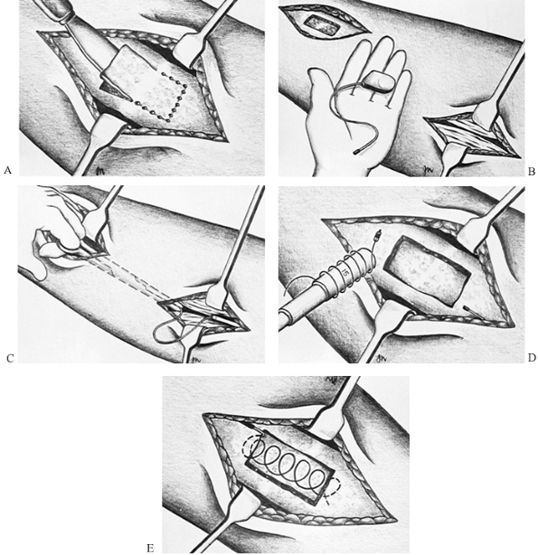
drill holes and then connecting them with a thin, sharp osteotome (Fig. 26.14A).![]() Figure 26.14. Insertion of implantable stimulator. A: Preparation of the defect in the bone. B: Insertion of the generator. C: Placement of the cathode lead in the nonunion. D: Preparation of the cathode. E: Insertion of the cathode.
Figure 26.14. Insertion of implantable stimulator. A: Preparation of the defect in the bone. B: Insertion of the generator. C: Placement of the cathode lead in the nonunion. D: Preparation of the cathode. E: Insertion of the cathode. -
Remove the window. Remove the underlying
fibrous tissue and open the medullary cavity of both the proximal and
distal fragments to the width of the original medullary cavity. This
encourages revascularization and creates space to insert the cathode. -
Identify a site for the generator, which
must lie at least 5 cm away from the cathode and beneath the deep
fascia. Sometimes this can be placed percutaneously through the
surgical site of the nonunion. If not, make a 3-cm-long skin incision
over the desired location for the generator, incise the deep fascia,
and then use an obturator or a Metzenbaum scissors to dissect between
the nonunion site and the generator site. Place the generator into the
wound beneath the deep fascia and pass the lead wire down to the
nonunion site. Be certain that this route is straight, as it simplifies
eventual removal, but leave some laxity in the line so that motion of
the joints adjacent to the operative site does not cause tension on the
wire (Fig. 26.14B, Fig. 26.14C). -
Using the cylindrical plastic guide
provided with the stimulator, measure the width of the defect in the
tibia and wind the titanium electrode around the guide to produce a
helix big enough to completely bridge the width of the canal at the
point of the nonunion. Use the guide to insert the helix into the
nonunion site in the medullary canal and remove the guide, leaving the
cathode helix in the defect (Fig. 26.14E).
Replace the window that was removed from the bone to secure the helix
in place. If there is adjacent internal fixation, be certain that the
cathode does not touch the internal fixation: Bone can be packed
between the two. -
Connect the lead to the coil, placing the
connector away from the bone so that it will disconnect when the
generator is later removed. -
Postoperatively, if internal fixation has
not been used, immobilize and proceed as discussed for noninvasive
electrical stimulation. If implants are present, follow the
postoperative treatment appropriate for the implant used. This device
cannot be used with intramedullary implants, as there would be no place
to locate the cathode. The generator usually remains active for up to 1
year. After that time, remove the generator by making an incision
directly over it and pulling gently in line with the connecting wire.
This will usually result in disconnection at the connector and removal
of the generator as well as its stainless-steel lead.
substantially since they were first introduced for clinical use in the
early 1980s, as most nonunions I encounter are better treated with
surgery. In spite of the low risk with noninvasive techniques, most
patients are anxious to get on with their lives and desire treatment
methods that will quickly return them to functioning and that carry a
higher success rate than the 74% to 79% union rates reported for
noninvasive electrical stimulation (5).
Therefore, my primary use is in delayed unions of the tibia for
patients who select electrical stimulation as an alternative to
surgical treatment, or in high-risk patients where surgery may be
contraindicated. PEMFs and capacitive coupling are about equally
efficacious, but capacitive coupling devices are more portable, they
are applied for 24 hours each day, and placement of the electrodes is
not as demanding as the placement of electromagnetic induction coils.
In addition, in inductive coupling, a fixation plate may “shadow” a
bone from the electromagnetic field if the width of the plate is
perpendicular to the plane of the central axis of the coil. Other
devices have become available that offer shorter treatment periods and
other advantages, but there is little in the literature supporting
their efficacy.
electrical stimulation describes outcomes varying from 74% to 79% in
more than 2,400 nonunions (1,5,8,25,26,28,44,66,70,91,92). I have been able to identify only two prospective, randomized, blinded studies in this literature. Sharrard (92)
treated 45 patients with delayed unions of the tibia between 16 and 32
weeks after fracture. They were placed in casts for 12 weeks and
treated with PEMFs. In one group, the coil was active and in the other,
inactive. He achieved a radiographic union rate of 25% in the active
group, but only 4% in the dummy group; additionally, 45% achieved
clinical union in the active group and only 12% in the dummy group.
These results were statistically significant. Scott and King (91)
reported the results of 21 long-bone nonunions, of which 10 were
treated with an active capacitive coupler and 11 were treated with an
inactive device. Six of those treated with the active device healed and
none healed with the inactive device. These results were significantly
different with a p value of 0.004.
stimulation is minor skin irritation at the electrodes in capacitive
coupling. This occurs in fewer than 3% of patients. Moving the
electrodes to a fresh site or rotating electrodes on a weekly basis
usually prevents this problem. Complications in the implanted device
are the usual complications expected of surgery, with the exception of
difficulties that might be encountered in removing the electrode. If
the connector is located too close to the nonunion site, it and the
connecting wire can be incorporated into
bone
so that when the generator is pulled on, the connecting wire shreds or
breaks off at the generator, or somewhere along the wire, and a portion
of it is left in the patient. If the surgeon feels that this must be
removed, then direct exposure of the wire down to the nonunion site may
be required.
prospective, randomized, double-blind study, showed that noninvasive,
low-intensity pulsed ultrasound can accelerate overall clinical and
radiographic healing in tibial shaft fractures by 38%. This echoed the
previous animal and clinical studies of Duarte (21), Pilla et al. (78), and Xavier and Duarte (104).
The specific mechanism by which ultrasound accelerates diaphyseal
fracture repair is unknown. Possibilities include mechanical
perturbation, and the direct stimulation of biological activity either
directly by mechanical deformation of the cell membrane or indirectly
by an electrical effect caused by cell deformation. Ryaby et al. (86)
have shown that low-intensity pulsed ultrasound modulates adenylate
cyclase activity and β-transforming growth factor synthesis. This has
led to a significant number of yet unpublished animal and clinical
studies over the past several years, which have suggested, but have not
yet proven conclusively, that ultrasound may have the ability to cause
nonunions to heal. At this time, ultrasound has not been approved by
the U.S. Food and Drug Administration (FDA) for treatment of nonunions.
popularized the treatment of nonunions by injection with autologous
bone marrow. This technique requires aspiration of autologous bone
marrow through large bore needles from the iliac crest, and then
injection of this into the nonunion site under fluoroscopic control.
The efficacy of this technique has not been proven, as no randomized
trials have been done. Connolly et al. (19)
treated 20 ununited tibial fractures. Ten received cast immobilization
and marrow injection, and eight of these achieved union. In the second
group of 10 fractures, intramedullary nails were inserted as well, and
all of this group achieved union.
has demonstrated the efficacy of combining percutaneous injection of
bone marrow and demineralized bone matrix in a canine model and in a
case report of healing a large nonossifying fibroma. I do not use this
method in my practice because multiple treatments are required and the
effectiveness is not sufficiently high to justify its use.
treatment of nonunions is a thorough evaluation of the patient, and of
the nonunion and the alignment of the limb segment involved, which
together lead to the decision to operate. If there is coexisting
malalignment, shortening, or joint stiffness that requires surgical
treatment as well, then the preoperative planning can be fairly
complex, as the methods for correcting each of these deficiencies must
be taken into account. The basic principles in reestablishing limb
length and alignment are discussed in detail in Chapter 32,
which focuses on the preoperative planning for Ilizarov procedures. The
preoperative planning for malunions is discussed later in this chapter.
the soft-tissue envelope over the nonunion site. Internal fixation and
bone grafting will not be successful unless the fracture site is well
vascularized or some method is undertaken to enhance vascularization.
In addition, operating through densely scarred, poorly vascularized
skin and deep tissues may lead to wound complications and infection
that could result in failure, even amputation. In circumstances where
the soft-tissue envelope is poor, consultation with an orthopaedic or
plastic surgeon with experience in local or free microvascularized
flaps may be indicated. These procedures may be required as a prelude
to the primary surgical treatment of the nonunion or as a concomitant
procedure (see Chapter 8, Chapter 35, and Chapter 36). The thought process applied to each of the implant possibilities and bone grafting are discussed next.
Medical Center, bone graft alone is used most commonly for
posterolateral bone grafting of the tibia (77).
Since the majority of tibial fractures at our center are being treated
today with locked, intramedullary nailing, this circumstance occurs
usually after a more severe open fracture, where a locked, reamed nail
is in place. If a small nonreamed nail is in place, we are more likely
to perform exchange reamed nailing (40,52).
In nonunions following weight-bearing cast treatment, when the location
of the fracture, overall alignment, or bone quality precludes
intramedullary nailing, we will bone graft from a posteromedial or
posterolateral approach, using continued weight-bearing cast
immobilization for stabilization. This approach is discussed in detail
in Chapter 31.
graft alone include fractures in good alignment with stable fixation
with plates or rods already in place, when revision
of the fixation is not necessary and inlay or onlay bone graft is felt to be sufficient to push the fracture on to union.
determined by the needs of the nonunion. The bone graft required may
vary from a small amount of pure cancellous bone to a large amount of
cancellous bone, cortical cancellous strips, or structural bicortical
and tricortical bone graft used to replace bone deficiency from the
injury itself or resulting from correction of deformity, such as
opening wedge osteotomy through a nonunion site in metaphyseal bone.
See Chapter 9 for details on bone grafting.
hypertrophic and well-vascularized nonunions where increasing the
stability of the fracture site alone will result in union (60,83,85).
Oligotrophic nonunions and all of the avascular nonunions require bone
grafting. Because I do not wish to risk failure, I routinely bone graft
all nonunions that I treat with plate and screw fixation. In
hypertrophic nonunions and in the occasional horse’s hoof nonunion,
reduction of the bony callus for cosmetic reasons, either to correct
deformity or to create a site for the plate, often provides sufficient
bone graft. This bone is frequently sclerotic and not nearly as bone
inductive or bone conductive as freshly harvested graft; therefore, I
harvest iliac crest bone graft in the vast majority of nonunions that I
plate. Plate and screw fixation combined with autologous bone graft is
applicable to all types of nonunions.
-
Position the patient so that the
appropriate iliac crest or other bone graft can be harvested without
having to reposition or reprep and redrape the patient. When large
amounts of graft are needed, the best source is the posterior iliac
spine, which is most easily harvested in the prone position but can
also be harvested from the uppermost crest in the lateral decubitus
position. When the nonunion must be treated in the supine position, the
graft of necessity will need to be harvested first. -
When exposing nonunions for plate
fixation and bone grafting, try to minimize subperiosteal stripping of
the bone in order to preserve its blood supply. Application of a plate
and bone graft usually requires exposure of only 50% of the overall
circumference of the bone. Try not to use retractors that result in
additional stripping. -
Once the nonunion is exposed, remove any existing hardware, which will interfere with treatment of the nonunion.
-
In very stable, fibrous nonunions where
there appears to be good blood supply to the bone ends [as demonstrated
by punctate bleeding (paprika sign) when the cortex is shaved with an
osteotome], a takedown of the nonunion site is usually unnecessary, as
the fracture will normally heal with compression plate fixation
combined with onlay bone grafting. -
If there is a synovial pseudarthrosis, if
deformity needs to be corrected, or if there is an unstable, loose,
fibrous union, remove all scar tissue in the fracture site, freshen the
bone ends, and shape them to optimize cortical contact. Open the
medullary canal fully on both the distal and proximal fragments. -
When debriding fracture sites, take
appropriate soft-tissue and bone cultures. Unless frank purulence is
encountered, I have not found Gram stains to be useful. Do not
administer preoperative antibiotics until these cultures are taken.
Once cultures are taken, administer appropriate intravenous antibiotics. -
Apply a plate to the fracture,
incorporating interfragmentary screw fixation across the fracture site
if possible. Whenever possible, I try to use an independent
interfragmentary lag screw so that biplanar fixation is obtained. In
the diaphysis of the large long bones such as the humerus, femur, and
tibia, use broad plates; in smaller bones such as the forearm and
fibula, use a 3.5 mm plate or the equivalent. -
For nonunions, I tend to use plates
somewhat longer than I would for the initial fracture, placing at least
four solid bicortical screws in each fragment. -
After the initial plate and
interfragmentary screw fixation has been completed, carefully stress
the fracture site under direct vision and examine for micromotion. If
gaping in the fracture site occurs with stressing of the plate with
your hand in the plane of the plate, supplemental fixation is needed.
If the surgical situation precludes the addition of a second plate,
then plan to use cast or brace immobilization postoperatively. In most
cases, I apply a second plate at right angles to the initial plate,
which is smaller in overall dimensions and shorter than the primary
plate to avoid excessive stress protection at the fracture site, and to
avoid a stress riser at the end of the plate. These supplemental plates
can usually be applied with minimal additional exposure because they
serve as tension bands to eliminate micromotion in the fracture site
and therefore do not need to be large. -
Petal the cortex with a small osteotome
for a distance at least equal to the diameter of the cortex at that
point on the proximal and distal fragment, and then apply a solid layer
of cancellous and/or cortical cancellous iliac crest bone graft along
this exposed surface. It does no good to apply a bone graft over the
top of the plate. Try to apply it on both sides of the plate construct
if this can be done without excessive soft-tissue stripping. -
Perform a meticulous closure of the wound. A suction drain is nearly always advisable.
-
Prior to closure, carefully examine the
nonunion site and the joints above and below to determine how much
motion can be allowed without placing excessive stress on the nonunion
site.
when designing the postoperative rehabilitation program. In a femur,
for example, if full extension and flexion to 90° cause micromotion at
the fracture site, plan to place the patient immediately after surgery
into a functional brace that will limit extension to -10° and flexion
to 80°. Continue this protection until bridging callus is seen across
the nonunion site and it is stable and nontender to clinical
examination.
resulting in blistering of the skin and even compartment syndrome. In
most cases, a bulky, well-padded splint postoperatively is important to
allow for swelling. Elevate the limb 10 cm above the heart and observe
it closely for swelling, which may require intervention.
more comfortable, replace the bulky dressing with a light dressing or
functional cast or brace as indicated. Begin a joint range-of-motion
and strengthening program as soon as possible, taking into account the
limitations of the strength of the construct used to repair the
nonunion. In all cases of plate fixation in the lower extremity, weight
bearing must be limited to the weight of the limb until bridging callus
across the nonunion site is seen on two radiographic views.
until the cultures are negative. If cultures are positive, continue
antibiotics for at least 6 weeks. I find consultation with an
infectious disease specialist helpful in determining the type and
length of antibiotic therapy.
nonunions in the mid diaphysis in the tibia and the femur, however, it
has been used in many bones including the malleoli (46).
It is not technically feasible in the forearm and does not work nearly
as well as plates in the humerus. Closed technique is particularly
advantageous, but it is usually difficult to perform in nonunions
because the medullary canal is sealed and callus at the fracture site
makes aligning the canal without opening the fracture exceedingly
difficult. Primary intramedullary nailing, therefore, usually requires
that the nonunion site be opened and the intramedullary canal
reestablished and realigned.
to compress the fracture site and lock the nail statically in
compression. This eliminates micromotion in the fracture site and
usually results in immediate relief of pain. If there is contact of 50%
or more of the cortical surface between the proximal and distal
fragments, weight bearing can progress rapidly if a large nail with 4.5
mm or larger transverse locking screws is used. I no longer treat
nonunions with dynamic nails, as they tend to leave instability in the
fracture site, particularly in rotation, which lowers the likelihood of
union in spite of weight bearing. If a nonunion is opened for reamed
intramedullary nailing, collect the reaming materials and apply them
around the fracture site for a bone graft. Bone defects and avascular
nonunions require autologous bone graft from the ilium as well.
Since the advent of interlocking nails, most of these occur in the
presence of static interlocking. The nonunion occurs either because of
the severity of the original injury, or because some factor in the
original nailing resulted in devascularization of the fracture site, or
because the fracture was nailed with a gap as a result of either bone
loss or inadvertent distraction of the fracture site. In some atrophic
nonunions, it appears that an osteoclastic response at the fracture
site results in resorption of bone, which also produces a gap.
cross-locking screws from one or both ends of the nail and then
allowing the patient to bear weight on the nail—has been advocated as a
method to eliminate the gap and stimulate union. Although this is a
very simple method and can lead to union in a significant percentage of
cases, it may not work in the tibia if the fibula has healed and
maintains distraction, or if weight bearing does not stabilize the
fracture and rotary instability continues. Another common error is to
remove the cross-locking screws nearest to the fracture site, which can
introduce not only rotary motion but also instability in other planes.
For example, in a nonunion of the femur that is below the mid
diaphysis, dynamize proximally rather than distally. The best
indication for dynamization is a nonunion of the femur or tibia that
already has a large reamed nail in place and where the fracture is
oblique so that weight bearing will cause increasing stability,
particularly in rotation.
either without reaming or with minimal reaming, to fix fractures of the
tibia, the femur, and occasionally the humerus, particularly in
patients with severe multiple injuries or open fractures. Occasionally,
the result is a nonunion with breakage of the nail or screws. In these
cases, exchange nailing is more difficult, and special techniques for
removal of broken nails and screws are required.
removed with the appropriate screwdriver. To remove the opposite side
of the screw, make an incision directly over the tip of the screw and
expose it. If sufficient screw tip is exposed, it can be removed with
commercially available screw removal instruments or grasped with a pair
of pliers and twisted out. When performing routine cross-locking, it is
always advisable to leave three to five threads protruding from the
opposite cortex, assuming that this will not cause painful soft-tissue
impingement in the event that removal of a broken screw is required. If
the broken section of screw is buried, then removal requires
overdrilling the broken segment with a hollow mill-reamer designed for
screw removal under fluoroscopic control. This often leaves a fairly
large hole in the bone. When repeat nailing is done, try to place the
nail beyond this hole to avoid a stress riser at the end of the nail.
segments depends on the type of nail—whether cannulated or solid—and
where the break occurs. In the femur, typical locations for nail
failure are (a) through the proximal cross-locking hole or at the
distal of the two proximal cross-locking holes where transverse locking
screws are present, (b) in the midportion of the nail at the fracture
site, or (c) in supracondylar fractures through the more proximal of
the two distal transverse cross-locking holes. If failure occurs
through the proximal half of the nail, then removal of the proximal
portion is easily accomplished with the standard nail removal
instrumentation. An “easy out” (a T-handled instrument with a tapered,
spiral-threaded tip), if it is long enough, can be used to remove the
distal portion after removal of the distal cross-locking screws.
ball-tipped reaming guide into the distal segment of the nail, with the
ball-tip outside the tip of the nail, and then to drive a second guide
down the inside of the nail to jam the first guide. Attaching a
vice-grip pliers or a T-handled pin holder facilitates removal. A third
technique, one that I have used successfully on a number of occasions,
is to fashion a hook from a coat hanger at home in my workshop using a
duplicate of the nail to make certain that the hook is ideally shaped
for hooking the distal end of the nail. This is sterilized and then
used in a fashion similar to the jammed guide pin technique. As a last
resort, a small window can be made in the bone just below the distal
end of the nail; the broken nail segment is then driven proximalward to
be grasped and removed. Usually, the plan is to place a larger reamed
nail for fixation. In this case, it is quite helpful to first ream the
proximal canal to a larger diameter to facilitate manipulation of the
instruments and removal of the broken nail segment.
the largest nail feasible for the bone involved to ensure adequate
strength of the implant, to improve cortical contact and therefore
stability, and to produce as much reaming material around the fracture
site as possible.
on nonunions in the upper extremity, I no longer use intramedullary
nails for the treatment of nonunions of the humerus. The single
exception is when there is a nonunion with an intramedullary nail
already in place. In these cases, closed reamed interlocked
intramedullary nailing avoids opening the fracture site; in the few
cases I have done this, it has worked 100% of the time. A
contraindication to this technique is severe osteoporosis because of
the high risks of fracture of the humerus and failure to obtain an
adequate hold with cross-locking screws.
indicated for nonunions that are accompanied by severe shortening and
require concomitant lengthening; nonunions in which there is major bone
deficiency that can be replaced only by segment transportation; and
nonunions where there is severe bone deformity and/or soft-tissue
contractures, which are best treated by Ilizarov techniques (17,36,37,38 and 39,90).
appropriate rate and frequency results in osteogenesis, which can
induce fibrous nonunions to heal. This will not work in synovial
pseudarthroses, which must be ruled out by a technetium bone scan, and
it does not appear to be efficacious in atrophic nonunions. The
technique utilized at the nonunion site is to distract the nonunion
approximately 5–10 mm and then to compress it, and to repeat this
sequence until new bone formation is elicited, at which time the
nonunion site is placed into compression. Throughout this process, the
patient is encouraged to bear full weight to induce physiologic stress
across the nonunion site, which also helps stimulate bone formation.
The success rate with this technique in North America has been
sufficiently low so that for most surgeons it is not the treatment of
choice for nonunions, except when open surgical techniques are not
suitable or are contraindicated, as discussed previously. In addition,
in gap nonunions where segment transport is used to close a gap, union
at the site between the transported segment and the static segment
tends to be quite slow; therefore, most surgeons bone graft the
junction site to accelerate union.
technique, so it is discussed in detail with each of the techniques in
the next three chapters. In general, however, the most difficult
decision is determining when to progress the patient’s rehabilitation
program, particularly passive manipulation of joints, resistive
exercises to build muscle strength, and weight bearing, because all
three rehabilitation activities stress the implants and nonunion site.
Active range of motion protected by a brace with the joints locked to
keep the range of motion within the safe zone, as discussed previously,
can usually be instituted in nearly all patients who are reliable. In
most cases, resistive exercises and passive manipulation of joints must
be avoided until early union occurs. With plates in the lower
extremity, weight bearing to the weight of the limb is usually possible
immediately, but progression beyond that point must be avoided until
union occurs. With intramedullary nails locked in compression and with
good bone contact, weight bearing can usually progress as tolerated.
to judge, particularly with plates, because if the reconstruction has
been done well the fracture site can often not be seen on the immediate
postoperative films. It can be helpful to establish intraoperatively
which particular view shows the fracture site best by examining it
under fluoroscopy. This view can then be used postoperatively to
monitor trabeculation and obliteration of the nonunion site. Otherwise,
monitoring the consolidation of the onlay bone graft usually provides
the best guide to union. Early union is heralded by bridging callus
along the surface of the nonunion seen on at least two 90° opposed
views. Full union is characterized by obliteration of the fracture
line, and increased maturation and density in the periosteal new bone
to resemble that of the nearby cortex. In any
case,
stable union usually requires a minimum of 3 months and often 6 months
or more. This is particularly the case in closed intramedullary
exchange nailing and where previous plate fixation has been converted
to an intramedullary nail.
in bone that is osteoporotic in longstanding nonunions or in the
elderly can be difficult. I have found the following techniques to be
useful:
-
In cancellous bone with an overlying thin
cortical shell in metaphyseal and epiphyseal areas, place large
cortical screws without tapping, to compress the cancellous bone around
the screw and provide more threads for purchase in the cortical bone
than cancellous screws do. -
In metaphyseal areas, use small-fragment
double plates placed at 90° to each other to provide a sandwich effect,
which adds stability.-
Avoid excessive periosteal stripping, as this has the risk of excessive devascularization.
-
When inserting cortical screws in this
application, run the screws from the two 90° plates close to each other
so that the threads of the screws cross-engage; this often provides
purchase where it would otherwise not be possible.
-
-
When these measures fail and the screws
still have inadequate purchase, inject liquid methylmethacrylate into
each screw hole and then reinsert the screw while the cement is soft.
This usually provides solid fixation. Do not allow the cement to enter
the fracture site or the joint. -
In the diaphysis, injecting cement into
the screw hole usually does not work well, because the cement tends to
run into the medullary canal or into the fracture site; this could
prevent healing. As a salvage procedure in an elderly patient when the
only other alternative is prosthetic replacement, I will pack cement
that is in the doughy phase into the medullary canal where the screws
will be placed, keeping it well away from the fracture site. Once the
cement is set, it can be drilled and tapped. Screw fixation is usually
superb.-
The difficulty with this technique is
that it markedly devascularizes the cortex and absolutely precludes
restoration of the medullary blood supply. -
Healing in these cases is totally
dependent on the periosteum and surrounding soft tissues. It cannot be
assumed that the fracture itself will heal, so a copious onlay bone
graft must be done in the hope that this will result in good union. If
this fails, then prosthetic replacement with a specialized prosthesis
may become necessary.
-
-
Other alternatives include the intramedullary plate discussed in Chapter 30
and the use of autologous or allograft cortical struts. The latter are
more successful and more readily available. Place these struts in the
intramedullary canal, or better yet, on the cortex opposite the plate,
and insert the screws into the allograft. Backup nuts and washers can
also be used, but they tend to crush osteoporotic bone unless an
allograft strut is utilized.
of acute and chronic osteomyelitis, pyarthrosis, and infected implants
is discussed in detail in Chapter 132, Chapter 133, Chapter 134 and Chapter 135.
Always attempt to control infection before treating the nonunion,
unless it is obvious that this is not possible. In an infected nonunion
of the tibia, for example, perform a thorough debridement of the
nonunion site, including the fistula tract and scarred soft tissue, and
remove all necrotic and infected bone as well as implants. Stabilize
with external fixation. Begin bactericidal antibiotics and monitor with
appropriate laboratory testing. As previously discussed, soft-tissue
procedures such as local rotation musculofascial flaps or free
microvascularized flaps may be necessary to revascularize the nonunion
site and to provide a good environment for future operative
intervention (54,76,102,103).
In 6–12 weeks, if there are no systemic or local signs of infection and
the wound has been clean and dry for at least 6 weeks, decide whether
treatment of the nonunion will be carried out with an external fixator
or by conversion to internal fixation with bone grafting (41).
cultures in a wound that is under control is possible, but this is the
exception rather than the rule. If the patient has a difficult
organism, such as a drug-resistant enterococcus, treatment of the
nonunion in the external fixator is indicated. Copious bone graft
should be applied and the external fixator checked and revised if
necessary to ensure excellent stability. If conversion to internal
fixation is deemed necessary, it is usually advisable to remove the
external fixator and to apply an appropriate cast to allow the pin
tracks to heal prior to surgery.
anatomic position is a malunion. Minor deviations of the alignment of
bones from anatomic, however, usually cause no symptoms or functional
deficit. The term malunion, therefore,
applies to fractures that heal with either shortening, malrotation, or
angulation, which produces unacceptable cosmetic deformity or
significant functional deficit, or it alters the contact stresses in
adjacent joints such that degenerative arthritis is more likely. There
is considerable controversy as to what constitutes malunion. Merchant (53),
for example, showed in a long-term study that considerable angulation
in the tibia is compatible with good function and does not predispose
to arthritis in the knee or ankle.
even minor malalignment may lead to functional complaints, particularly
in high-performance athletes. What constitutes sufficient malalignment
to justify surgical correction will be addressed on a bone-by-bone
basis in the following chapters.
extremities, but it can be a significant problem in the lower
extremities. Walking with a shortened extremity produces a pelvic tilt
and angulation at the lumbosacral junction, which can lead to chronic
low back pain. This can be corrected by wearing a shoe lift; however,
lifts over 15 mm in thickness usually must be applied, at least in
part, to the outside of the shoe. This is expensive and often
cosmetically unacceptable, and it cannot be done to some types of
shoes. The lifts stiffen the soles and increase the weight of the shoe,
which is a problem in sportswear. In addition, the increased height of
the ankle off the floor predisposes to sprains of the ankle. Shortening
of less than 2.5 cm in the lower extremity can usually be managed by
shoe lifts, whereas shortening of 2.5 cm or more may require
correction, particularly in active young people.
and, in the lower extremity, to reestablish an anatomic mechanical axis
of weight bearing between the hip and ankle joints (34,49,50,56,58,59,64,72,73,95,106).
Sometimes the goal may be to actually overcorrect alignment to
redistribute the contact stresses in the knee as treatment for
posttraumatic degenerative arthritis. Even if alignment is well
corrected, the patient will not be happy if she has continued joint
dysfunction, particularly stiffness. Concomitant arthroscopy to treat
internal derangement of joints, to reconstruct ligaments, and
soft-tissue procedures to restore motion, must be considered. The
ultimate goal is to restore as much function as possible.
Occasionally, a segmental fracture will result in a dual-plane
deformity, as when a proximal fracture heals with
deformity
in one plane and the more distal fracture heals with deformity in
another plane, and independent correction of deformity at each fracture
site is necessary (96).
The vast majority of malunions, however, are single fractures with
angulation in a single plane. In the past, we considered these to be
two-plane deformities, because angulation is seen on the AP and lateral
views. However, they are really single-plane deformities that are
greater than can be seen on the AP and lateral radiographs alone.
however. Take plain AP and lateral radiographs of both the affected and
the normal extremity, making certain that both are aligned with the
central beam of the x-ray. Use as long a tube distance as possible and
incorporate a radiographic ruler to assist in measurements. Either
include in those views the joints above and below, or take separate
views. In the lower extremity, determine the mechanical axis by taking
weight-bearing AP and lateral radiographs, using long cassettes to
include the hip and ankle joints. When trying to compare the axis of
the knee joint relative to the ankle joint, it is often helpful to take
independent AP films with the central beam at right angles, or with a
10° caudal tilt at the knee and AP at the ankle.
evaluation of nonunions described earlier in this chapter applies also
to malunions. Try to measure the degree of angulation and establish the
plane in angular deformities. Compare rotation in the affected limb to
that in the abnormal limb: This is often the best guide to malrotation.
The same is true for shortening, which is discussed below.
difficult, particularly if there are contractures of the ankle, knee,
or hip joint. I use all of the following methods before deciding on how
much to equalize leg length.
-
Measure leg lengths from the anterior/superior iliac spines to the medial malleoli and bottom of the feet.
-
Measure leg lengths at the medial
malleoli by marking the malleoli with a felt tip pen whose mark will
transfer easily. With the pelvis level, pull down on both feet and
touch the malleoli together, noting the leg-length discrepancy between
the two marks. -
Stand the patient and place measuring
blocks under the short side until the pelvis is level and the patient
feels comfortable. I often shift the blocks back and forth in
increments of 1/8 to ¼ inch, without allowing patients to see what I am doing, to establish what correction they prefer. -
Confirm the measurements with
radiographs. AP views of the hips and pelvis, knees, and ankles with a
radiographic ruler in place at the maximum tube distance is usually
accurate as long as the patient does not move during the examination.
You may want to personally supervise these films to be certain that
they are accurate. Next, place the blocks under the short side,
correcting the discrepancy, and take a weight-bearing AP view of the
pelvis, being certain that the cassette is level with the floor and the
patient is standing perfectly erect. Comparison of all these
measurements and discussion with the patient will usually lead to a
decision to undertake a given correction. I rely mostly on the standing
block measurements.
of angulation alone, without addressing translational deformity, will
leave the mechanical axis disturbed. In addition, there is almost
always some malrotation and some degree of shortening. The radiographic
appearance of these deformities, how to assess the mechanical axis, and
how to measure deformity are discussed in detail in Chapter 32.
Use the vector analysis technique described there to determine
angulation and translation, and use the true mechanical axis technique
to establish the mechanical axis.
focuses on the Ilizarov technique, but the process for characterizing
the deformity is the same. The major difference in preoperative
planning is that in the Ilizarov technique a simple transverse
osteotomy is nearly always done, and the correction is taken through
the distraction site by adjustment of the external fixator. This gives
a great deal of latitude, as even if there are miscalculations,
adjustments can be made in the external fixator frame as the deformity
is corrected, to achieve good alignment.
internal fixation is in place and the skin closed, adjustments are very
difficult to make, especially after closing wedge osteotomies, for
example. Therefore, incomplete or inaccurate correction may require
reoperation.
In preoperative planning, take into account how changes in angulation
and rotation will affect overall length of the extremity.
Rotate and manipulate superimposed images of the major bone fragments
until the desired bone configuration and limb alignment are achieved.
This can be done with tracing paper, clear x-ray film, or a digitizing
tablet coupled to a microcomputer (Fig. 26.15, Fig. 26.16, Fig. 26.17, Fig. 26.18 and Fig. 26.19,).
For the sake of accuracy, include the joints proximal and distal to the
osteotomy in the drawing. In the lower extremity, do mechanical axis
drawings. If the deformity is unilateral, use a contralateral tracing
as a template. This allows a prediction of the outcome (Fig. 26.15C, Fig. 26.16B and Fig. 26.17B). With the overlay
technique, before and after views can be compared and different
proposed solutions weighed, to select the plan that will best restore
the mechanical axis and equalize limb lengths.
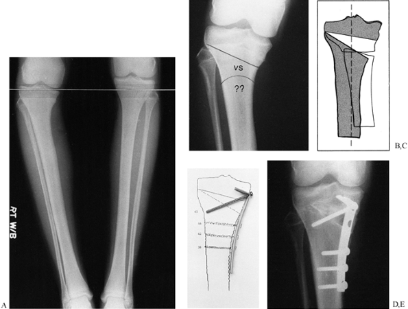 |
|
Figure 26.15. A: Preoperative standing film shows 20° varus deformity of right tibia and 2 cm limb-length discrepancy. B: Options for surgical treatment include intraligamentous incomplete opening wedge and crescentic osteotomy. C: Overlay comparison of the two options in (B). The opening wedge (shaded areas) will gain an additional 1 cm of length while restoring the mechanical axis. D:
The drawing serves as a template for sizing the tricortical iliac graft and preoperative contouring of the semitubular “hook plate.” The fibula was not cut. E: The hook plate was compressed over the tricortical graft and an interfragmentary screw was placed through the plate. By placing the screw at the apex, a wide range of angles are available. (From Stevens PM. L-Plate Fixation for Osteotomies. Orthopedics 1991;14:767.) |
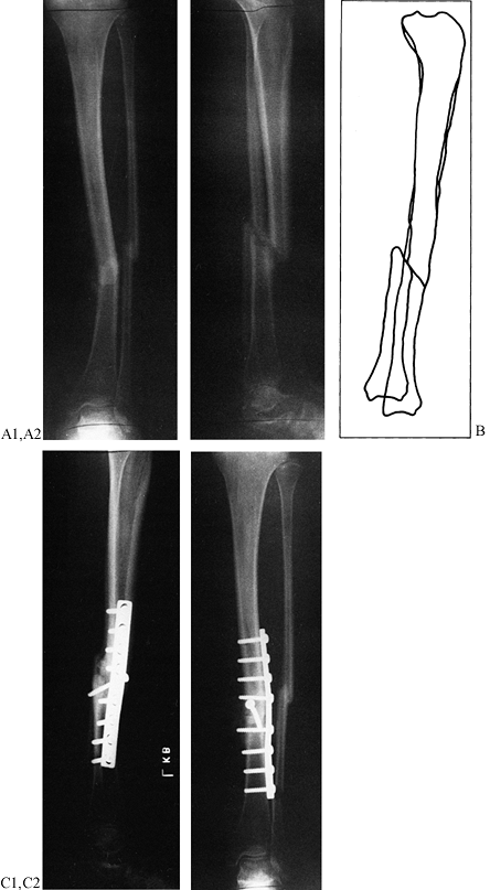 |
|
Figure 26.16. A: Nonunion of the tibia, presenting as a two-plane deformity with 13° of varus, translocation, and 1.2 cm of shortening. B: Overlay drafting provides direct comparison with contralateral tibia serving as a template. C:
After oblique osteotomy and realignment with the femoral distractor, the tibia was fixed with an interfragmentary screw and contoured neutralization plate. |
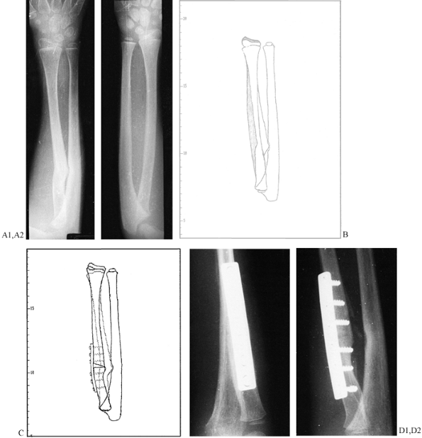 |
|
Figure 26.17. A: Radial malunion with synostosis, 6 mm shortening of the radius, wrist pain, and 0° pronation/supination. B: The difference in radial length and alignment is readily apparent on this digitized overlay comparison (left side is white; the template is shaded on the normal right side). C:
The optimal plan calls for an opening wedge osteotomy through the radial malunion, excision of the synostosis with fat interposition, and stabilization with a precontoured DC plate. D: Intraoperatively, 70° each of pronation and supination were gained, while full radial length was restored with an autogenous tricortical bone graft. The transverse cut made insertion of an interfragmentary screw impractical. |
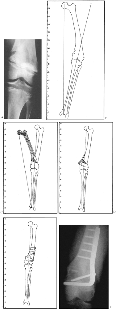 |
|
Figure 26.18. A:
This 13-year-old girl sustained a closed fracture of her distal femur, which led to asymmetrical closure of her distal femoral physis, resulting in 30° of varus and a 4.5 cm limb-length discrepancy. B: The digital tracing of her full-length standing film demonstrates the real versus the desired mechanical axis, and the lateral slope of her knee. C: A 32 mm medial opening wedge osteotomy would normalize the mechanical axis while restoring 3 cm of length. D: Although a medial 90° blade plate is more convenient to apply, it would be unacceptably prominent. E: Therefore, a 95° blade plate was applied through a lateral incision. The lateral femoral physis was curetted to prevent recurrent varus. F: By the fifth postoperative month, the patient had solid clinical and radiographic union, with symmetrical alignment and a 1 cm residual length discrepancy. |
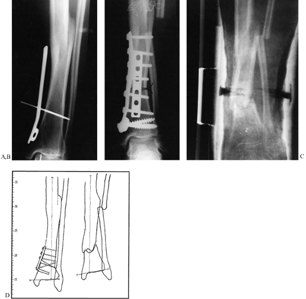 |
|
Figure 26.19. A: Intraoperative “plan” for correction of 10° varus malunion of the tibia. B:
The transverse diaphyseal osteotomy was unstable after application of a medial buttress plate without an interfragmentary screw. An anterior plate was added, requiring excessive soft-tissue stripping. Still, no lag screw was used; note the persistent gap. C: Wound slough and an infected malunion resulted. The limb was salvaged with debridement and electrical stimulation. This unfortunate sequence of events could have been avoided by good preoperative planning. D: (Left) In retrospect, a preplanned, incomplete opening wedge supramalleolar tibial osteotomy, secured with tension band fixation, would have safely afforded excellent correction. The length discrepancy would have been 1.2 cm. (Right) The result in this case was 12° of valgus and a limb-length discrepancy of 3 cm. |
are uncommon (and in the sagittal plane even more so), and a single
drawing suffices. Plan the degree of valgus or varus correction within
the context of mechanical alignment (Fig. 26.15C).
If there are deformities at two locations, combined or compensatory, a
double osteotomy may yield the best biomechanical solution, keeping the
joints horizontal and restoring the mechanical axis (Fig. 26.18D).
Simple deformities in the sagittal plane often produce an unphysiologic
arc of joint motion. Examples include dorsal tilt after a Colles’
fracture, recurvatum of the knee, and ankle deformities. Wedge or
displacement osteotomies can be planned on a tracing of the lateral
radiograph. Maximum flexion and extension views help to delineate the
desired degree of correction.
As already discussed, all deformities at a single level are in fact in
a single plane, but they are commonly midway between the AP and the
lateral planes and thus are oblique. For example, femur fractures tend
to angulate in an anterolateral direction, and tibias can be in almost
any plane. It is important to understand the precise plane of the
deformity and the actual angulation (see Chapter 32).
This can be done by vector analysis or by using geometric calculations.
Although these deformities can be corrected by approaching the
angulations in the different planes sequentially, as described in the
discussion of the AO oblique osteotomy below, a more precise technique,
although more technically challenging, is to do a single-plane
osteotomy that corrects the entire deformity.
deformity is to examine the limb segment under fluoroscopy, rotating
the limb until there is no deformity seen on the x-ray film. This marks
the plane of the deformity. Taking a second radiograph at exactly 90°
to this plane permits measurement of the true angulation.
malalignment. Determination of the degree of malrotation is based on
the methods already described. Correction of malrotation in complex
deformities can be incorporated into a single-plane osteotomy, or done
in a stepwise fashion if the osteotomy is transverse or oblique as
discussed in the next section. In some cases, a CT scan and a
computer-generated, three-dimensional model may be beneficial for
visualizing the necessary correction.
identify the location of any structural bone grafts required, and place
drawings of the hardware to be used. Hardware templates available from
manufacturers are quite useful. If the preoperative plan is clear-cut
and changes are not anticipated, preoperative contouring of plates can
save considerable time in the operating room. Plan for alternative
methods of fixation and be certain that appropriate implants are
available. Also have available a simple universal external fixator and
a femoral distractor, which may assist in intraoperative control of
fragments pending definitive internal fixation.
intraoperative fluoroscopic control is invaluable, particularly for
reestablishing the mechanical axis in the lower extremities. Because
fluoroscopy does not give a large field of view, however, final
alignment must be confirmed with radiographs that include the joints
above and below. To facilitate the fluoroscopy, use fully radiolucent
operating tables that allow free passage of the C-arm from the pelvis
to the foot.
Personal preference may play a role, but place a premium on simplicity,
stability, and predictability. Corrective osteotomies are best done at
or near the site of deformity, which is determined by the point of
intersection of the axes of the proximal and distal segments. The
farther from this point an osteotomy is done, the more difficult it is
to normalize the mechanical axis and the more likely it is that a
zigzag compensatory deformity will result, which may be undesirable.
Other factors demand consideration, however, including the condition of
the soft tissues, history of infection, fixation problems, and
anticipated healing time. If there are extenuating circumstances, a
distant correction and compensatory deformity may be acceptable.
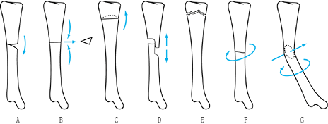 |
|
Figure 26.20. Types of osteotomies. A: Opening wedge. B: Closing wedge. C: Displacement. D: Stepcut. E: Crescentic (dome). F: Transverse derotation. G: Oblique (single plane).
|
it is important to ascertain that the plane of cut is transverse to the
long axis of the bone to avoid inadvertently producing a frontal or
sagittal deformity. Although simple to perform, a transverse osteotomy
is relatively unstable and is not ideally suited for interfragmentary
compression. It resists an axial load but is inherently weak if
subjected to torsion or bending loads. Angular corrections can be
difficult to control (Fig. 26.19).
In the diaphysis, locked intramedullary fixation permits load sharing
and excellent stability. If an open osteotomy is performed, requiring
extensive exposure and periosteal stripping, intramedullary reaming and
nailing may produce unacceptable devascularization and delayed healing.
In such instances, plating or external fixation is preferable.
Transverse metaphyseal osteotomies may produce cortical stepoff and the
risk of intra- or postoperative invagination of the smaller fragment,
resulting in overcorrection. The cancellous bone may provide marginal
anchorage for screws, wires, and staples (17). Consider blade-plate fixation, double plates, or supplemental external splintage.
using percutaneous “closed” intramedullary osteotomy with locked nail
fixation (see Chapter 30 for details). For
open osteotomies, it is critical that the degree of correction be
accurately controlled and determined intraoperatively. Knight (45)
describes a precision guide-pin technique for wedge and rotatory
osteotomy of the femur and tibia. In 85% of 47 osteotomies, his
correction was within 3° of the operative goal. Pulisetti et al. (79)
describe a method using CT, in which the malrotation angle value in
degrees can be translated into millimeters on the circumference of the
diaphysis; they feel this virtually eliminates error in correcting
rotation.
-
Before making the osteotomy, place a 2 mm
Kirschner (K-) wire, or a stronger pin, into the proximal fragment in
an area that will not interfere with the internal fixation and where
soft-tissue distortion will not bend the pin. -
Place a similar pin distally, directly in line with the proximal pin. This establishes the starting point.
-
Preoperatively bend a K-wire into a V to match the angle to be corrected. This will serve as an intraoperative guide.
-
Mark the bone where the osteotomy will be
made. Draw a longitudinal line on the bone across the osteotomy, or
mark it with a slight nick from an osteotome to provide an additional
reference. -
To facilitate fixation, a plate, if one
is to be used, can be molded to the bone at the site of correction; it
can be temporarily fixed to the proximal fragment with a single screw
and then rotated out of position for the osteotomy. Once the osteotomy
is done, this plate can be rotated back into position and secured to
the distal fragment with a bone-holding forceps or a single screw for a
preliminary check on the correction. -
Make the transverse osteotomy. Rotate the limb to the corrected angle and secure the osteotomy as described previously.
-
Always sterilely prep and drape the
opposite limb so that comparisons of rotation can be made. Do that at
this time to be certain that the correction is accurate. -
Complete the fixation using a stable construct, and close and dress the wound.
-
Finally, examine the anesthetized patient
after wound closure and take final radiographs to be certain that the
correction is as desired. If it is not, reprep and redrape and make
adjustments as needed. If the surgery has been performed precisely,
following these instructions, the need to reoperate should be minimal
or nonexistent.
variation of the transverse osteotomy. The most commonly used closing
wedge osteotomy is a high tibial osteotomy performed to treat
unicompartmental arthritis of the knee. Its advantages are simplicity,
stability, and rapidity of healing. Disadvantages are that it can
affect soft-tissue balance if close to joints, and it will result in
some shortening.
In addition, if an excessively large wedge is taken, overcorrection is possible.
closing wedge, because the degree of deformity to be corrected can be
established easily before committing to an irreversible cut. Also, the
correction angle can be easily adjusted intraoperatively until the
correct position is obtained. It offers the advantage of some gain in
length. The disadvantages result from the fact that the opening wedge
must be filled by a bone graft, which slows healing, nonunions can
occur, and the intercalary bone graft used must remodel before full
weight bearing can begin (Fig. 26.20A, Fig. 26.20B).
performed in the cancellous bone of the metaphyses; it can be done in
diaphyseal bone as well but with higher risk because of its slower
healing. I have used this osteotomy most commonly in the proximal and
distal tibia and occasionally in the distal femur. The ideal graft is
harvested as a tricortical graft from the anterior ilium, using the
cortical surface of the superior rim of the ilium as the portion of the
graft that supports the opposing cortices at the osteotomy site (see Chapter 9). The following technique is for an opening wedge osteotomy of the proximal tibia.
-
Under fluoroscopic control, place a
K-wire parallel to the tibial plateau and just slightly superior to the
site planned for the osteotomy. -
Using a water-cooled oscillating saw with
a long blade, and providing appropriate protection for the soft
tissues, make a transverse osteotomy parallel to the K-wire and at a
right angle to the long axis of the tibia in the other plane. Stop 10
mm short of the opposite cortex. -
Gently correct the deformity, and plan to
create a green stick fracture of the opposite cortex. If there is
significant resistance to straightening the bone, drill the opposite
cortex through the osteotomy with several drill holes to weaken it. -
Try to maintain the continuity of the
cortex and soft tissues on the opposite cortex, as this significantly
increases the stability of the osteotomy and hastens healing. -
When the correction is achieved, prop
open the osteotomy with an appropriate-size prop. I have available an
assortment of plastic blocks in 5 mm increments, which are useful for
temporarily holding the osteotomy open. -
Measure the mechanical axis and take AP and lateral radiographs to be certain that the correction is complete.
-
Measure the width of the opening wedge
thus produced and the length of bone wedge needed, and harvest as many
of these as are necessary to completely fill the defect. In the tibia,
usually three wedges from the iliac crest are required. -
Drive the tricortical iliac crest wedges
into the osteotomy site and stabilize it with a single large plate or
with two small fragment plates placed at roughly right angles to each
other. The osteotomy and grafts should be in compression at the
completion of the fixation. -
Take final radiographs to confirm position.
placement of the first K-wire is identical to that for an opening wedge
osteotomy. The surgical technique then continues as follows:
-
Place a second K-wire parallel to the
first at the angle of wedge to be removed. Be certain that the K-wires
are placed so that the narrow end of the osteotomy will just meet the
opposite cortex. -
With the oscillating saw, make a
transverse cut parallel to and just inferior to the proximal K-wire,
being certain that the plane of the saw remains parallel to the joint.
Stop just short of the opposite cortex (this is just slightly farther
than for the opening wedge osteotomy). -
Now make the second saw cut, watching the
blade carefully under fluoroscopic control to be certain that it stays
parallel to the first cut and will meet the first cut precisely at the
opposite cortex. A free saw blade placed in the first osteotomy
provides a useful reference. -
Remove the wedge by placing a thin
osteotome into the proximal osteotomy and a second into the distal
osteotomy: Use these to pry out the wedge. -
Completely close the osteotomy and
temporarily fix it with a plate as for the opening wedge osteotomy, or
with a wire inserted across the osteotomy site. -
Evaluate the alignment discussed
previously, and complete fixation of the osteotomy with a plate and
screws. An external fixator can be used as well, but I prefer internal
fixation. If the osteotomy is in the mid diaphysis, perhaps an
intramedullary nail can be used if the overall alignment of the canal
has been established.
offers several advantages. It can correct all deformities with a single
cut. It presents a broader surface area for healing, has superior
bending and rotational stability, and can easily be compressed with an
interfragmentary lag screw. By inserting the screw through a plate, the
rigidity of fixation is increased by approximately 25%. (In the
diaphyseal region, where both cortices must be cut, use a contoured
neutralization plate.) However, the planning and execution are
challenging (80,87). The plates can be difficult to apply, but they can be effective for a rotational deformity. The
oblique osteotomy is especially useful in the metaphyseal region.
-
Make an incomplete cut close to the
joint, leaving an intact osteoperiosteal hinge for stability; a plate
can then be applied in a tension-band fashion (Fig. 26.15, Fig. 26.21A, Fig. 26.21D). The addition of an interfragmentary screw further increases stability.![]() Figure 26.21. A:
Figure 26.21. A:
Preoperative drawing for a patient with traumatic cubitus varus. The
plan calls for minimal exposure, incomplete osteotomy, and tension band
fixation; a 16 mm base equals a 30° wedge. B: Delineation of planned wedge with K-wires. C: Intraoperative confirmation of correction. D:
Screws with washers are placed before osteotomy. The oscillating saw is
guided by K-wires. Gradual closure of the gap is achieved, leaving a
medial hinge for stability. -
Plan the cuts to avoid a cortical stepoff.
-
Add or remove bone wedges to adjust the length and the mechanical axis (Fig. 26.15).
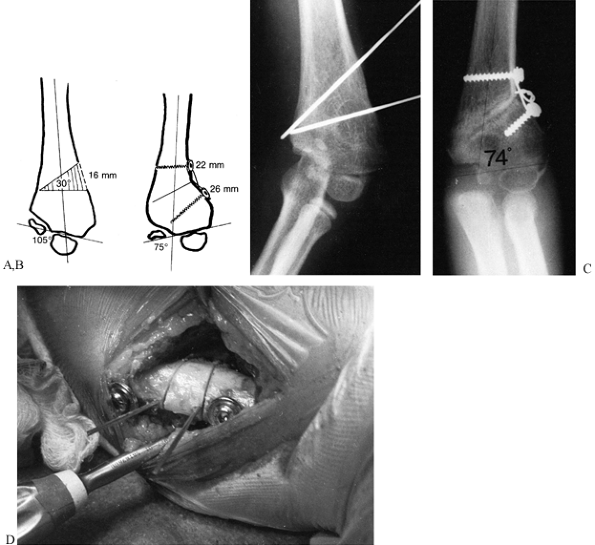
For proximal or distal tibial corrections, it is generally not
necessary to cut the fibula, unless rotation is also being corrected.
angular change required. In the proximal tibia, an intraligamentous
opening wedge osteotomy offers the additional advantage of improving
knee stability. In the immature patient, a one-plane or two-plane
deformity in conjunction with a partial physeal arrest is often
present. A metaphyseal opening wedge osteotomy in a patient with less
than 50% physeal closure facilitates the exposure for an
epiphysiolysis. Realignment also reduces the eccentric load on the
recovering physis. If the percentage of physeal
closure
precludes an epiphysiolysis, a transphyseal closing wedge osteotomy
prevents recurrence of the deformity. In the event of a malunited
Salter-Harris III or IV fracture, an osteotomy through the old fracture
site permits anatomic reduction using tracings of the contralateral
joint as a template.
With one cut, angular deformity in the frontal and sagittal planes,
shortening, and malrotation can be corrected in a stepwise fashion (Fig. 26.22).
The major disadvantage is that it requires considerable soft-tissue
exposure, which can lead to devascularization of the tips of the
proximal and distal fragments. I have had two AO osteotomies that were
technically well done but went on to a nonunion that was difficult to
recover from, so I use this osteotomy infrequently.
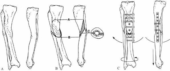 |
|
Figure 26.22. The AO method for triplane osteotomy. A:
Malunion of the tibia and fibula with 15° of valgus deformity, 15° of recurvatum, 15° of external rotation, and 2 cm of shortening. B: All of these deformities can be corrected by a single oblique, frontal-plane osteotomy made at the point of maximum deformity, at an angle of 60°. After the initial cut is made, remove a wedge from the distal fragment to correct the recurvatum; then remove a second wedge from the distal fragment to correct the malrotation. (A skilled surgeon can make both corrections with a single cut.) Next osteotomize the fibula. C: Restore length with a femoral distractor. Fix the osteotomy with two or three interfragmentary compression screws. Apply a neutralization plate with three bicortical screws above and below the osteotomy to either the lateral or medial surface. (I prefer the lateral surface.) |
challenging and difficult to plan, is the single-plane osteotomy
described by Sangeorzan et al. (87), and independently by Rab (80).
The technique is based on a mathematically precise calculation that
characterizes the deformity. It allows the determination of an axis
about which the distal fragment can be rotated to make it coincident
with the proximal fragment. A plane perpendicular to this axis allows a
single surgical cut to be made that will permit correction of the full
deformity (Fig. 26.23). The technique requires
four steps: precisely defining the location and angular measurements of
the deformity in all planes; finding the angle of osteotomy required to
correct the deformity; locating the starting point of the osteotomy
referable to the transverse plane; and then cutting along this plane
with an oscillating saw and rotating the distal segment relative to the
proximal segment to bring them into the corrected position. Because the
osteotomy is oblique, interfragmentary screw fixation works well,
particularly when combined with a neutralization plate. The details of
this technique are rather complex and beyond the scope of this chapter,
but the articles by Sangeorzan et al. (87) and Rab (80) are excellent, and they provide additional references of interest.
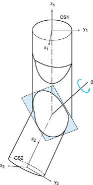 |
|
Figure 26.23.
A Sangeorzan mathematically directed single cut osteotomy. This drawing is a model of the malunion, which is shown as a cylinder with a localized bend and twist. The process of determining the deformity involves assigning a coordinate axis to each end of the bone where the proximal portion, CS1, represents the normally aligned segment and CS2 is the malaligned distal segment. The axes are superimposed at the site of the deformity. All components of the deformity can be corrected by rotating CS2 about an axis, represented here as beta to make CS1 coincident with CS2. The axis, beta, is determined mathematically. The osteotomy is made in a plane perpendicular to the beta axis, which is represented by the shaded area in this drawing. The oblique interface of this osteotomy lends itself to lag-screw fixation. (For the details on the mathematical calculations, see Sangeorzan BJ, Sangeorzan BP, Hansen ST Jr, Judd RP. Mathematically Directed Single-Cut Osteotomy for Correction of Tibial Malunion. J Orthop Trauma 1989;3:267.) |
or epiphyseal cancellous bone, where the irregular nature of the bone
and the cut provide good inherent stability, and the broad surface area
and cancellous bone lead to rapid healing (Fig. 26.24).
It is much more difficult to use in cortical bone, and I no longer use
it in the diaphysis. It is ideal for correcting deformity near joints
that are in
a
single plane, preferably the frontal plane. In preoperative planning,
be certain that an undesirable shift of the mechanical axis will not
occur. Some gain in length due to the correction of the deformity is
possible but usually minimal. Although external fixation can be used,
most require plate fixation (see Chapter 30). The following osteotomy is performed for correction of a pure valgus deformity of the ankle.
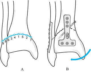 |
|
Figure 26.24. Crescentic (dome) osteotomy of the distal tibia. See text for explanation.
|
-
Expose the distal tibia through an
anterior approach. If correction of the fibula is needed as well, plan
to incorporate it into the dome osteotomy. -
The dome osteotomy usually works best if
the concave side is directed toward the joint or distally. Localize the
osteotomy at the site of the major deformity in the distal tibia,
leaving enough room to secure plate fixation in the distal fragment. -
After anterior exposure of the tibia and fibula just proximal to the ankle joint, draw out a gentle curve (Fig. 26.24A), the radius of which will permit correction of the deformity. (Figure 26.24 shows a moderate, 15° varus deformity, and it depicts incorporation of the fibula, which is often not necessary.)
-
Use appropriate-size drill points (in the
figure, they are 3.5 mm in diameter, but this depends on the size of
the bone). Insert the first drill point at the apex of the dome (in the
figure, this is drawn on the anterior tibia), and drill it through the
anterior and posterior cortices, keeping it exactly at 90° to the axis
of the proximal shaft of the tibia. -
Next, place two additional drill points
at a point midway between the first drill point and the medial and
lateral cortices, keeping them exactly parallel to the first drill
point. -
Add more drill points to fill in the
intervals, spacing them about 5 mm apart (follow roughly the numbered
sequence shown in the figure). Use the initial drill point as a guide
to be certain that all the drills are parallel to each other, producing
a perfect dome. In a typical adult tibia, about five or six drill
points can be placed. It is very important that these all be parallel
to each other along the roof of the dome osteotomy. -
When all drill points have been placed,
remove them and connect the drill holes both anteriorly and posteriorly
with a slim, ¼-inch (Hoke) osteotome (Fig. 26.24B). Do this by completing the osteotomy anteriorly first and then running the osteotome across the tibia to the posterior cortex. -
Next, rotate the osteotomy to obtain
correction and impact it. The combination of drill holes and osteotome
cuts produces two opposed cogwheels. At the appropriate point of
correction, these can be interdigitated and
P.881
then
impacted, producing a surprisingly stable osteotomy. Obtain initial
fixation with either K-wires or a single screw. I prefer to use at
least two interfragmentary screws across the osteotomy for the primary
fixation (see Chapter 30). -
Obtain plain radiographs and determine
the mechanical axis to be certain the correction is as desired.
Complete the fixation by stabilizing it with a neutralization plate on
the tibia. -
If the fibula has been osteotomized, use a 1/3-tubular plate on the fibula.
-
Correction of a juxtaarticular deformity
of this type is technically easier to do with a frontal plane oblique
osteotomy. The advantages of the dome are that it requires less
soft-tissue stripping and patients can bear weight immediately in most
cases. Healing is also more rapid than with an oblique osteotomy.
axis intraoperatively with the fluoroscope is to use a Bovie cord from
the electrocautery unit, because this is radiopaque, readily available,
and sterile for use in the operating field. Be certain to attach the
cord to the drapes so that sufficient length is available to reach from
the hip to the ankle.
-
To establish the mechanical axis, center
the C-arm over the femoral head and hold the Bovie cord so that it is
located dead center on the femoral head. Mark this position on the skin. -
While holding the Bovie cord under
tension, locate it directly over the center of the ankle mortice,
visualizing the location on the fluoroscope, and mark this on the skin
as well. Hold the Bovie cord on the skin so that parallax is minimized. -
Being careful not to move the Bovie cord
from the center of the hip and ankle, use the fluoroscope to visualize
the knee and record the image, print it, and place it on the operating
room x-ray view box. On the normal side, the cord should pass directly
through the center of the knee, which is usually just on the lateral
side of the medial tibial spine. -
Make a similar determination on the abnormal side that is to be corrected.
-
Once the correction is achieved in
surgery, repeat this procedure on the operated side, to ensure that the
mechanical axis is comparable to the normal or unoperated extremity. If
bilateral deformities are being done, locate the cord directly in the
center of the knee. -
Bone grafts are not usually required for
osteotomies unless an opening wedge osteotomy is being performed. This
may require several tricortical grafts harvested from the anterior
superior iliac spine (see Chapter 9). In this case, be certain to prepare and drape the iliac crest.
It consists of a transverse metaphyseal osteotomy in which the
periarticular fragment is rotated, impacting one corner of the
metaphysis into the medullary canal of the other fragment. This
transforms bending loads into compressive loads while preserving length
and improving joint alignment.
a stepcut osteotomy may be convenient. However, it requires significant
exposure, which devascularizes the bone ends, and fixation may be
tenuous. Rotational and angular corrections are limited (Fig. 26.20D, Fig. 26.20E and Fig. 26.20F).
mechanical construct, early motion of the extremity is safe and
desirable. Base the range of motion permitted, degree of weight
bearing, and level of use of the extremity on the intraoperative
assessment of the stability of the reconstruction. Avoid overstressing
the implants until healing occurs.
cannot yield sufficient information on which to base the decision to
perform an osteotomy. For instance, ankylosis of a joint may preclude
the successful realignment of a limb after an osteotomy, and a flail
limb or unstable joint may not fare well after an osteotomy. When
performing a varus-producing osteotomy of the upper femur, you must
anticipate how the distance from the articular surface of the hip joint
to the trochanter is altered; a patient with “good containment” but
restricted abduction and a marked Trendelenburg gait is not likely to
be pleased with the clinical outcome. A preexisting limb-length
inequity may be exacerbated by an otherwise satisfactory angular
correction. The radiographic examination is critical, so adequate radiographs are a prerequisite to planning.
Although there are innumerable reasons for failure of reconstructive
osteotomies, most of them are avoidable. Perceptual and technical
errors can be averted if you abide by the principles described here and
pay attention to details.
essential for consistent and predictable results. The use of hardware
templates prevents embarrassing and costly mistakes in the operating
room. Although a preoperative plan is no guarantee of success, it
narrows the range of potential intraoperative errors and allows
contingency plans to be formulated. Improper positioning and draping
compromises surgery at every step, as does inadequate exposure.
Excessive exposure is equally reprehensible and may lead to a poor
outcome (Fig. 26.19).
possible progression of the deformity because the pathomechanics
continue (Fig. 26.18). Overcorrection is
equally undesirable. Strive to achieve a neutral mechanical axis and to
balance the forces around a joint. The key to avoiding intraoperative
pitfalls is prevention, thorough planning, adequate exposure,
intraoperative control with radiographic documentation, and stable
fixation.
neurovascular structures by careful dissection, gentle retraction, and
extensile approaches. Vigorous retraction and excessive periosteal
stripping are to be condemned. Never close wounds under tension;
consider delayed closure or use of appropriate flaps when the wound is
excessively swollen. Perform neurolysis or fasciotomies if indicated.
use of perioperative antibiotics and suction drainage of the wound.
Treat infection aggressively with debridement and appropriate
culture-specific antibiotics. If the osteotomy remains stable and the
implant is intact, the hardware should be left in place. Implant
failure or loss of fixation and alignment warrant reoperation with
revision of fixation. If there is infection, consider external
fixation. The long-term implications of overcorrection or
undercorrection should be recognized and discussed with the patient,
because residual deformities have the same pathomechanical significance
as the original deformity. Use bone graft in osteotomies when the risk
of delayed nonunion is high.
scheme: *, classic article; #, review article; !, basic research
article; and +, clinical results/outcome study.
RI, Naseer M, Abel EW. Capacitively Coupled Electrical Stimulation
Treatment: Results from Patients with Failed Long Bone Fracture Unions.
J Orthop Trauma 1998;12:510.
CAL, Pilla AA, Pawluk RJ. A Nonoperative Salvage of Surgically
Resistant Pseudarthroses and Nonunions by Pulsing Electromagnetic
Fields. Clin Orthop 1977;124:128.
CT. Advanced Clinical Applications of Electromagnetic Field Effects:
Bone and Cartilage. In: Brighton CT, Pollack SR, eds.Electromagnetics in Biology and Medicine. San Francisco: San Francisco Press, 1991.
CT, Okereke E, Pollack SR, Clark CC. In Vitro Bone Cell Response to a
Capacitively Coupled Electrical Field. The Role of Field Strength,
Pulse Pattern, and Duty Cycle. Clin Orthop 1992;285:255.
CT, Schaffer JL, Shapiro DB, et al. Proliferation and Macromolecular
Synthesis by Rat Calvarial Bone Cells Grown in Various Oxygen Tensions.
J Orthop Res 1991;9:847.
G, Pilla A. Electromagnetic Modulation of Biological Processes:
Influence of Culture Media and Significance of Methodology in the
Calcium-Uptake of Embryonal Chick Tibia In Vitro. Calcif Tissue Int 1984;36:167.
JF, Guse R, Tiedeman J, Dehne R. Autologous Marrow Injection as a
Substitute for Operative Grafting of Tibial Nonunions. Clin Orthop 1991;266:259.
S, Van Ostenbridge J. Differential Response of Cell Membrane–Associated
and Lysosomal Enzymes to Pulsating Electromagnetic Fields. Trans Bioelectr Repair Growth Soc 1983;3:66.
TW, Degnan GG, Turen CH. The Use of Computer Tomographic Scan to Assess
Femoral Malrotation after Intramedullary Nailing—A Case Report. Clin Orthop 1992;279:258.
JL, Brighton CT, Heppenstall RB, et al. Detection of Synovial
Pseudarthrosis by 99mTc Scintigraphy: Application to Treatment of
Traumatic Nonunion with Constant Direct Current. Clin Orthop 1981;161:15.
JL, Friedenberg ZB, Brighton CT, Black J. Temporal Course of Bone
Formation in Response to Constant Direct Current Stimulation. J Orthop Res 1985;3:137.
ZB, Roberts PG Jr, Didizian NH, Brighton CT. Stimulation of Fracture
Healing by Direct Current in the Rabbit Fibula. J Bone Joint Surg Am 1971;53:1400.
B, Klaue P. Mechanical Stability and Post-Traumatic Osteitis: An
Experimental Evaluation of the Relation Between Infection of Bone and
Internal Fixation. Injury 1977;9:23.
CR, Cummings KD, Clark LC, et al. Augmentation of Bone Healing via
Electrical Stimuli. In: Brighton CT, Black J, Pollack SR, eds.Electrical Properties of Bone and Cartilage. New York: Grune & Stratton, 1979:155.
JD, Ryaby JP, McCabe J, et al. Acceleration of Tibial Fracture-Healing
by Non-invasive, Low-Intensity Pulsed Ultrasound. J Bone Joint Surg Am 1994;76:26.
DS, Pita JC, Marquez JF, Madruga JE. Partition of Calcium Phosphate and
Protein in the Fluid Phase Aspirated at Calcifying Sites in Epiphyseal
Cartilage. J Clin Invest 1968;47:1121.
GA. The Tension-Stress Effect on the Genesis and Growth of Tissues. I.
The Influence of Stability of Fixation and Soft-Tissue Preservation. Clin Orthop 1989;238:249.
GA. The Tension-Stress Effect on the Genesis and Growth of Tissues. II.
The Influence of the Rate and Frequency of Distraction. Clin Orthop 1989;239:263.
GA, Devyatov A, Kamenin VK. Plastic Reconstruction of Longitudinal Bone
Defects by Means of Compression and Subsequent Distraction. Acta Chir Plast 1980;22:32.
R, Judet J, Roy-Camille R. La Vascularisation des Pseudoarthroses des
Os Longs d’après une étude Clinique et Expérimentale. Rev Chir Orthop 1958;44:5.
WJ. The Use of Supplementary Electronic Bone Growth in Primary and
Secondary Lumbosacral Fusions. In: Brighton CT, Black J, Pollack SR,
eds.Electrical Properties of Bone and Cartilage: Experimental Effects and Clinical Applications. New York: Grune & Stratton, 1979.
L, Baurret L, Majeska R, Rodan G. Adherence and DNA Synthesis Changes
in Hard Tissue Cell Culture Produced by Electric Perturbation. In:
Brighton CT, Black J, Pollack SR, eds.Electrical Properties of Bone and Cartilage. New York: Grune & Stratton, 1979:443.
DC, Hillier TM, Carter RF, et al. Experimental Delayed Union of the Dog
Tibia and Its Use in Assessing the Effect of an Electrical Bone Growth
Stimulator. Clin Orthop 1977;128:340.
S. Mechanical and Technical Principles of the Internal Fixation of
Corrective Osteotomies. In: Hierholzer G, Muller KH, eds.Corrective Osteotomies of the Lower Extremity after Trauma. New York: Springer-Verlag, 1986.
DB. Treatment of Un-united Fractures by Onlay Bone Grafts without Screw
or Other Fixation and without Breaking Down of the Fibrous Union. J Bone Joint Surg 1947;29:946.
JT, Matthew J, Pilla AA, Duarte-Alves P. Low-intensity Pulsed
Ultrasound Modulates Adenylate Cyclase Activity and Transforming Growth
Factor Beta Synthesis. In: Brighton CT, Pollack SR, eds. Electromagnetics in Medicine and Biology. San Francisco: San Francisco Press, 1991:95.
BJ, Sangeorzan BP, Hansen ST, Judd RP. Mathematically Directed
Single-Cut Osteotomy for Correction of Tibial Malunion. J Orthop Trauma 1989;3:267.
G, King JB. A Prospective, Double-Blind Trial of Electrical Capacitive
Coupling in the Treatment of Non-union of Long Bones. J Bone Joint Surg Am 1994;76:820.
WJW, Sutcliffe ML, Robson MJ, MacEachern AG. The Treatment of Fibrous
Nonunion of Fractures by Pulsing Electromagnetic Stimulation. J Bone Joint Surg Br 1982;64:189.
S, Sansen W, Mulier JC. Experimental Study on the Electrical Impedance
of Bone and the Effect of Direct Current on the Healing of Fractures. Clin Orthop 1976;120:264.
JJ, Connolly JF, Strates BS, Lippiello L. Treatment of Nonunion by
Percutaneous Injection of Bone Marrow and Demineralized Bone Matrix: An
Experimental Study in Dogs. Clin Orthop 1991;268: 294.
JJ, Huurman WW, Connolly JF, Strates BS. Healing of a Large
Nonossifying Fibroma after Grafting With Bone Matrix and Marrow: A Case
Report. Clin Orthop 1991;265:302.