
III – Hand/Wrist > Chapter 16 – Distal Radius Fractures: External
Fixation and Supplemental K-Wires
commonly encountered injuries presenting to the emergency room setting.
Understanding the normal distal radius anatomy is essential for the
treating physician. The outcome of management of the unstable distal
radius fracture is directly related to successfully identifying,
reducing, and stabilizing the various fragments. Restoring articular
congruity and the relation between the distal radius and the
surrounding skeletal structures, while avoiding the complications of
treatment, are key considerations.
medial articular surface of the radius and the corresponding articular
head of the ulna. There is a considerable normal variation in length,
defined as positive ulnar variance (ulna length is greater than the
radius) and negative ulnar variance (ulna length is less than the
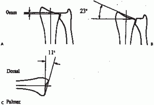
radius). Radial inclination is the angle of the surface, as identified
from the radial styloid to the medial articular surface. Normal is 22
degrees with a range of 13 to 30 degrees. The volar tilt is the angle
of the surface from the dorsal to the volar surface as seen on the
lateral radiograph. The average is 11 degrees with a range of 0 to 28
degrees. The scaphoid and lunate fossas are the articular surfaces that
correspond with their adjacent carpal bones, and the sigmoid notch is
the articulating surface with the ulna head (Fig. 16-1).
 |
|
FIGURE 16-1. Radiographic parameters of radial length (also referred to as ulnar variance) (A), radial inclination (B), and volar tilt (C) used for purposes of description and treatment.
|
radius. Most of these classifications attempt to subdivide this injury
into predictable fracture patterns that may be useful in determining
treatment
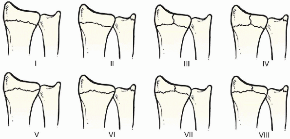
options. The earliest and most common classification is the Frykman
classification in which the radius fracture is assessed with respect to
articular involvement and whether there is an associated ulnar styloid
fracture (Fig. 16-2).
Despite the popularity of this classification, there is little gained
toward insight into treatment planning or prediction of outcome. Eight
types of fractures were described.
 |
|
FIGURE 16-2.
Frykman classification. The distal ulna is not fractured in types I, III, V, and VII. Intraarticular fractures are represented by types III, IV, V, VI, VII, and VIII. |
intraarticular and extraarticular fractures with nine patterns of
increasing complexity. Other classifications are the Rayhack, Mayo, and
Fernandez systems.
various numbers or combinations of numbers. The basic concept of most
distal radius classifications is to establish three factors, which is
also the basis of my classification: articular involvement, direction
of displacement, and stability. These can be easily remembered and
apply to most fractures of the distal radius, allowing an effective
treatment plan.
|
TABLE 16-1. RECOMMENDED TREATMENT PLANS
|
|||||||||||||||||||||||||||
|---|---|---|---|---|---|---|---|---|---|---|---|---|---|---|---|---|---|---|---|---|---|---|---|---|---|---|---|
|
|||||||||||||||||||||||||||
defined as residual shortening of greater than 5 mm, dorsal angulation
greater than 10 degrees, comminution of greater than 50% of the
metaphyseal region, or bicortical fragmentation.
there has been a higher associated incidence of more comminuted
unstable distal radius fractures in younger active patients. The
majority of these fractures are of the intraarticular dorsal displaced
unstable (IDU) type, requiring closed reduction and external fixation.
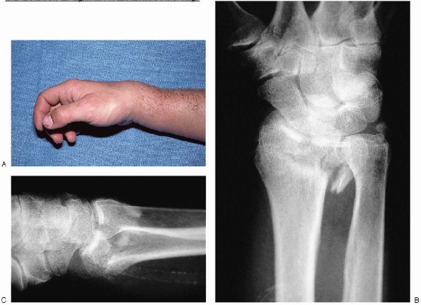
conjunction with radiographic correlation is essential initial
management. Standard radiographs are obtained in the posteroanterior
(PA), lateral, and oblique views (Fig. 16-3).
Comparative views of the unaffected contralateral side are also
recommended. This enables the surgeon to determine the normal radial
length, inclination, and volar tilt for each individual patient,
because an acceptable degree of variability exists within the
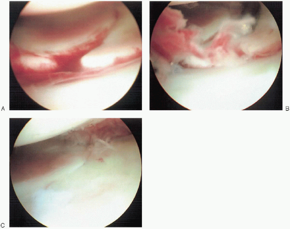
population. If an associated intercarpal ligament injury is suspected,
then a magnetic resonance imaging (MRI) or intraoperative arthroscopy
may be warranted (Fig. 16-4). It
is essential to encourage the patient to begin active range of motion
exercises for the digits, elbow, and shoulder before surgical
intervention. This diminishes the likelihood of progressive stiffness
and functional limitations.
 |
|
FIGURE 16-3. A: Clinical appearance of acute displaced distal radius fracture. Anteroposterior view (B) and lateral view (C) of underlying unstable distal radius fracture.
|
-
External fixator
-
Blunt-tipped external fixation half-pins
-
Appropriately sized drill bit and power drill
-
0.062-inch smooth K-wires
-
Bone graft substitute as needed
-
Intraoperative fluoroscopy
-
Surgical arm board
fracture with respect to restoration of radial length, inclination,
volar tilt, and articular alignment mandates the use of fluoroscopic
equipment. Application of the external fixation device requires the
appropriate drills, blunt skeletal half-pins, and external
fixation
frame of the surgeon’s choice. Supplemental Kirschner wire fixation has
proven to add to fracture stability and is straightforwardly inserted
with a power wire driver. If bone graft or bone graft substitute is
needed, one should confirm that the proper surgical tools or products
are available.
 |
|
FIGURE 16-4. Prereduction (A), evacuation of fracture hematoma (B), and postreduction arthroscopic views (C) of an unstable intraarticular fracture of the distal radius.
|
anesthetic with supplemental intravenous sedation. The patient is in a
supine position with the arm abducted to the side of the body at 90
degrees. The surgeon can comfortably sit within the inner side of the
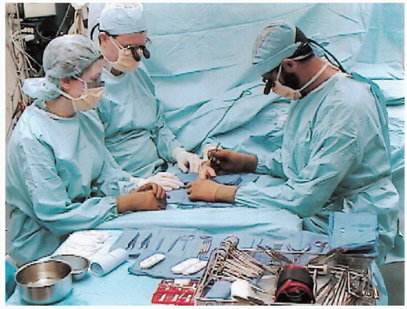
arm table extension, with the assistant opposite (Fig. 16-6). The
surgeon must avoid placing the forearm in a position of hyperpronation
in an attempt to improve visualization during pin insertion, because
this can lead to poor pin placement or malreduction at the fracture
site.
inserted using a percutaneous technique, the unacceptably high
incidence of associated complications related to malpositioning of the
pins and related soft tissue injury have led to the more commonly used
limited incision technique of half-pin insertion. The pins are inserted
into the index metacarpal proximal shaft and the radial shaft,
approximately 3 to 4 cm proximal to the fracture.
 |
|
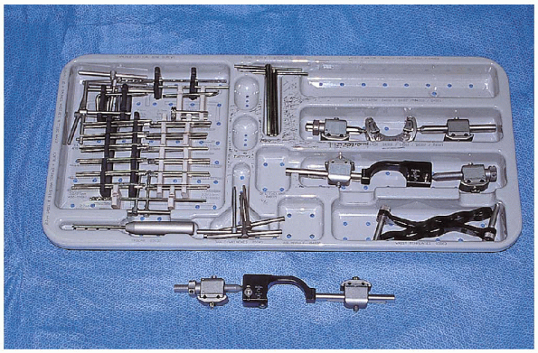
FIGURE 16-5.
Equipment for distal radius fracture: tray consists of drills, screws, trocar, clamps, wrist templates, and T-wrenches. The external fixator is shown below. |
 |
|
FIGURE 16-6. Customary operative setup and patient arm position for surgical management of distal radius fracture.
|
length of the external fixator should be clearly identified before
making the skin incisions, because this will determine the amount of
distraction that the fixator is able to achieve. If the proximal
incision site along the radial shaft is too proximal in location, the
fixator length may prohibit obtaining sufficient ligamentotaxis (Fig. 16-7).

an adequate anesthetic level has been achieved, the entire arm is
prepped and draped in a standard manner. More severely deformed wrists
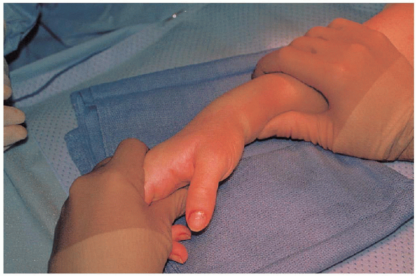
are initially aligned through primary, gentle closed manipulation (Fig. 16-8).
The arm is exsanguinated with a compressive elastic bandage, and a
well-padded tourniquet is then inflated over the proximal arm to an
appropriate level. The planning of pin placement for the fixator is
aided through the proper positioning of the fixation device along the
radial side of the forearm before incisions (Fig. 16-9).
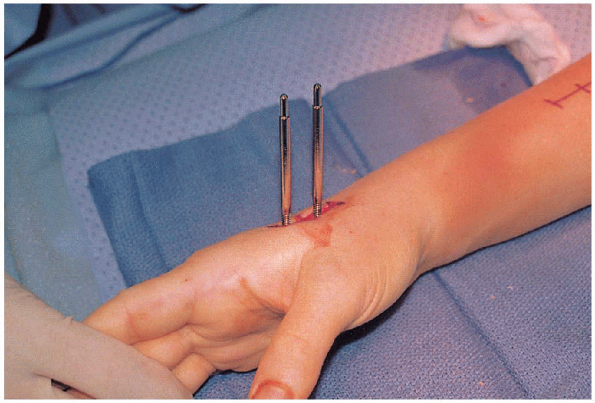
The index metacarpal is approached through a 2-cm longitudinal incision over the dorsal radial base (Fig. 16-10). The terminal branches of the radial sensory nerve are well protected,
because the first dorsal interosseous muscle and periosteum are
minimally reflected.
 |
|
FIGURE 16-7. Use of external fixation device to ensure proper proximal pin placement.
|
 |
|
FIGURE 16-8. Initial closed manipulation of the distal radius fracture for gross reduction before application of external fixation frame.
|
Thisdecreases the likelihood of unicortical drilling with the related
complications of potential pin loosening, infection, or iatrogenic
metacarpal fracture. After predrilling the pin sites,
the pins are manually inserted while maintaining the correct pin alignment.radial shaft pins are then placed using a similar technique of
insertion. Again, a 2-cm longitudinal incision is created along the
radial shaft proximal to the fracture site, with the lateral
antibrachial cutaneous nerve branches protected.
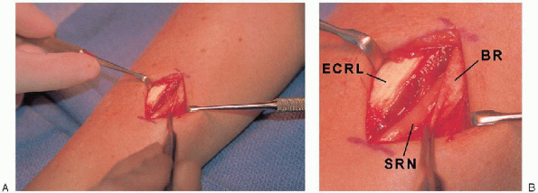
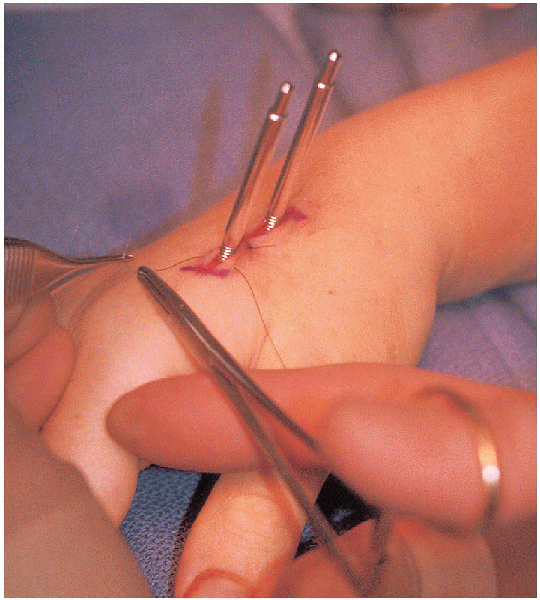
The deeper dissection reveals the radial sensory nerve as it pierces
the fascial layer between the brachioradialis and the extensor carpi
radialis longus (Fig. 16-11).
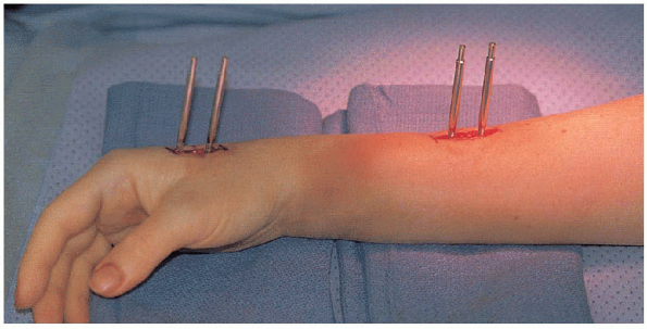
The pins are inserted between the extensor carpi radialis longus and brevis, thereby avoiding the radial sensory nerve. Accurate bicortical pin insertion is equally important at this location (Fig. 16-12).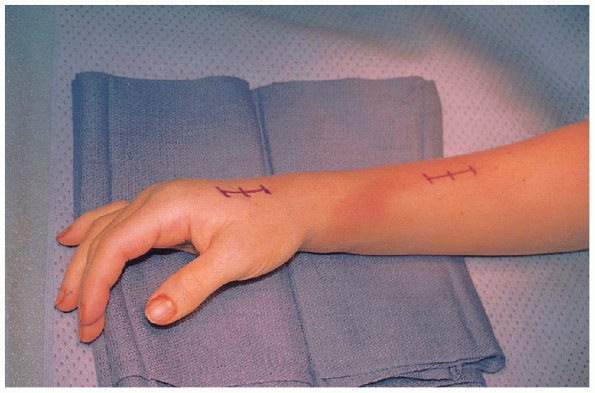 |
|
FIGURE 16-9. Marked incision sites for external fixation pin placement.
|
 |
|
FIGURE 16-10. Distal half-pin placement along the dorsoradial border of index metacarpal.
|
and placement confirmed with the intraoperative fluoroscopy unit (Fig. 16-13),the wounds are irrigated and closed before application of the external
fixation frame. This allows for better wound repair without interfering
with the closure (Fig. 16-14).
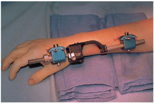
Most frames have a sliding clamp component that allows for distraction (ligamentotaxis) across the wrist joint (Fig. 16-15). Ihave found it useful assisting in the reduction with gentle
longitudinal traction applied to the fingers, while countertraction is
maintained at the 90-degree flexed elbow. Finger trap apparatus along
with a weight and pulley system has also been previously described with
similar success.
neutralized from the surface of the radius through ligamentotaxis,
closed manipulation of the fracture can be performed. Often, the
residual dorsal angular deformity prevails, despite restoration of
radial length and inclination. The fixator is temporarily adjusted in a
flexed position, allowing for a greater correction of a volar tilt. By
manual reduction of the distal fragments, with possible intrafocal
pinning, the correction of volar tilt can be obtained. Several of the
newer external fixators have a mechanical ability to assist in
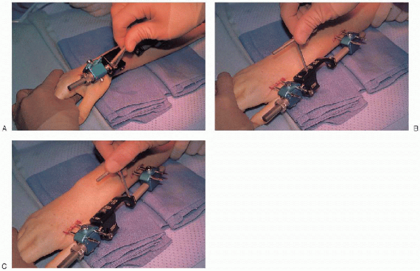
restoring volar tilt and radial inclination and rotational alignment (Fig. 16-16).
 |
|
FIGURE 16-11. A: Radial nerve is identified and protected before placement of the proximal half-pins. B: BR, brachioradialis tendon; ECRL, extensor carpi radialis longus tendon; SRN, radial sensory nerve.
|
 |
|
FIGURE 16-12. Completion of half-pin placement for the external fixation frame.
|
the radial styloid fragment and into the intact radial shaft, acting as
a buttress support for the fracture. If intrafocal pins are to be
added, care is taken to avoid penetrating the extensor tendons. This
may require a small stab incision and blunt surgical spreading through
the soft tissue before pin placement.
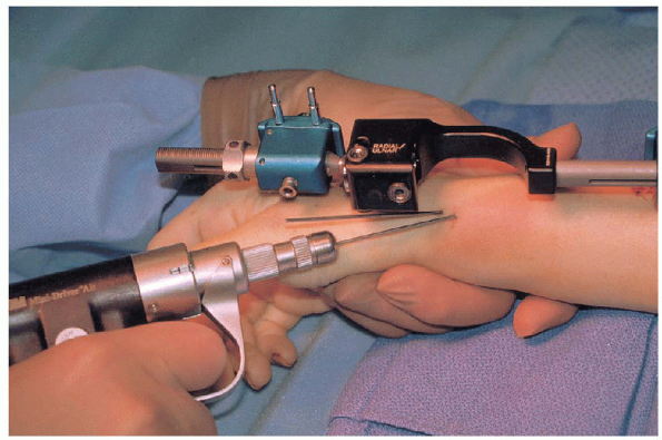
prefer to insert two to three wires in a diverging pattern from the
styloid or from the dorsal radial border of the distal fragment into
the radial shaft to add to the stability of the configuration and
thereby lessen the demands of the external fixator (Fig. 16-17).
Althougha transverse wire can be safely placed from the radial styloid to the
medial fracture fragment, oftentimes this medial fragment is comminuted
with little or no cortical bone purchase.
 |
|
FIGURE 16-13. Intraoperative fluoroscopic assessment of distal pins (A) and proximal pins (B) with good alignment.
|
the fixator can be restored to a neutral alignment, avoiding the flexed
posture required for primary fracture reduction. If the radiographs
reveal malreduction of the fracture despite optimal frame and wire
application, a limited open reduction and additional bone graft or bone
graft substitute is strongly suggested. This can be performed through a
small incision over Lister’s tubercle with blunt surgical spreading
through the soft tissue until the fracture is encountered. The extensor
pollicis longus should be decompressed from within Lister’s tubercle to
prevent potential attritional rupture. Often a Freer elevator can
augment the elevation of the fracture fragments before insertion of the
bone graft. Fluoroscopic imaging or direct inspection of the articular
surface through a dorsal capsulectomy confirms final reduction.
 |
|
FIGURE 16-14. Pin incision sites are repaired before application of frame.
|
this procedure is to overdistract the carpus through excessive
ligamentotaxis. This commonly leads to the complications of stiff
digits with residual loss of motion, loss of wrist flexion and
extension arc, and possibly reflex sympathetic dystrophy (RSD).
 |
|
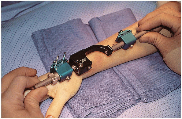
FIGURE 16-15. Initial placement of external fixation fame after distraction is achieved through the sliding couple clamp.
|
 |
|
FIGURE 16-16. Frame allows for radial and ulnar deviation (A), dorsal and volar alignment (B), and pronation and supination (C) at the fracture site.
|
techniques that I have routinely performed to ensure avoidance of
overdistraction and the subsequent complications.
most reliable technique is a passive finger flexion test. Once the
fixator is in place and the fracture is reduced, the surgeon passively
flexes the patient’s metacarpophalangeal joints along with simultaneous
flexion of the interphalangeal joints. If the fingers can be passively
flexed to the level of the proximal palmar crease without excessive
force, there is no excessive distraction across the wrist joint.
However, if there is a great degree of difficulty in passively flexing
the digits, then extrinsic extensor tendon tightness is present, which
is directly related to overdistraction.
 |
|
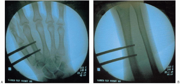
FIGURE 16-17. Insertion of 0.062-inch K-wires from styloid into intact radial shaft.
|
additional secondary evaluation tool of ligamentotaxis after fracture
reduction. Based on my experience, the distance of the radiocarpal (RC)
joint space and the midcarpal (MC) joint space should be measured on
standard anteroposterior (AP) fluoroscopic views. If the ratio of the
RC:MC joint was 2:1 to 1:1, most patients fell within the safe zone of
distractive force across the wrist (Fig. 16-19).
If there was greater than a 1:1 RC:MC ratio (i.e., 1:2 RC:MC), then the
volar radioscaphocapitate and radiolunotriquetral ligaments may be
overdistracted and can potentially lead to the common complications of
stiffness.
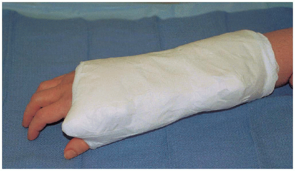
have found that a dry sterile bandage surrounding the fixator
half-pins, along with dressing changes and pin care every 2 weeks, has
eliminated the need for daily patient care and has allowed for
successful healing with a paucity of complications
in most patients (Fig. 16-20).
In the unlikely event that a superficial infection is encountered,
local wound care is performed on a daily basis with oral antibiotics
prescribed. It is rare to encounter a case of osteomyelitis and the
need for premature removal of the fixator along with debridement and
intravenous antibiotics.
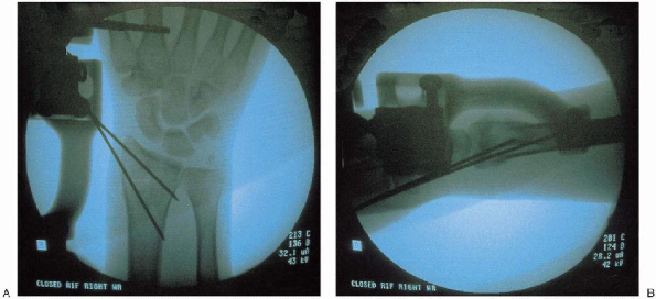 |
|
FIGURE 16-18. Postreduction intraoperative fluoroscopic assessment of posteroanterior (A) and lateral (B) views, confirming restoration of radial length, inclination, volar tilt, and articular congruity.
|
 |
|
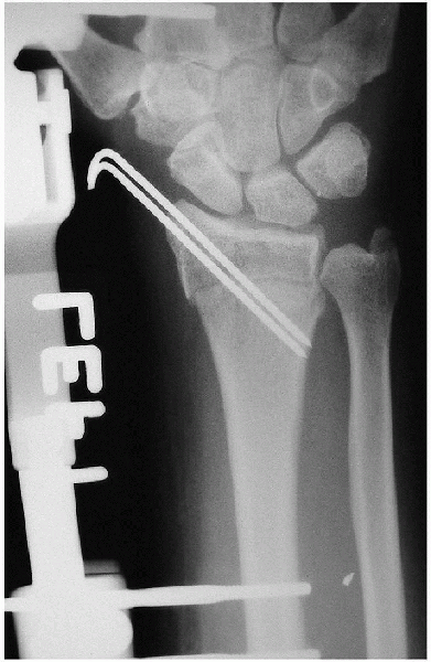
FIGURE 16-19.
Anteroposterior radiograph of distal radius fracture after closed reduction and external fixation with supplemental Kirschner wire. Radiocarpal and midcarpal articulations are seen without overdistraction. |
 |
|
FIGURE 16-20. Postoperative dressing.
|
 |
|
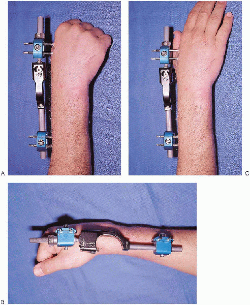
FIGURE 16-21. Postoperative clinical views of maintained flexion (A and B) and extension of digits (C) after proper application of external fixation with appropriate ligamentotaxis.
|
period, it is imperative that finger, elbow, and shoulder range of
motion exercises be instituted (Fig. 16-21). If
there appears to be slow progress in regaining an acceptable arc of
motion, then a more comprehensive occupational therapy program is begun.
Once adequate healing is observed clinically and radiographically, the
fixator and pins can be removed under a local anesthetic. It is not
uncommon for the radiographic appearance of fracture bridging to lag
behind clinical assessment of healing without point tenderness at the
previous fracture site. Therapy is advanced to include wrist range of
motion and subsequent strengthening.
Displaced intra-articular fractures of distal radius: a comparative
evaluation of results following closed reduction, external fixation and
open reduction with internal fixation. Injury 2000; 31: 75-79.