
Editors: Berquist, Thomas H.
Title: Musculoskeletal Imaging Companion, 2nd Edition
Copyright ©2007 Lippincott Williams & Wilkins
> Table of Contents > Chapter 7 – Shoulder/Arm
Chapter 7
Shoulder/Arm
Thomas H. Berquist
Protocols
Key Facts
• Routine radiography
|
||||||||
• Arthrography
|
||||||||
|
P.439
Suggested Reading
Berquist TH. MRI of the musculoskeletal system, 5th ed. Philadelphia: Lippincott Williams & Wilkins; 2006:557–656.
P.440
P.441
Fractures/Dislocations: Proximal Humeral Fractures
Key Facts
-
Fractures of the proximal humerus usually occur in the elderly.
-
Proximal humeral fractures account for 5% of all skeletal fractures.
-
Fractures in the elderly usually are caused by a fall.
-
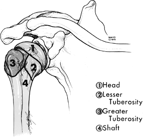
Fractures tend to follow the physeal
lines dividing the humerus into four parts: humeral head, greater
tuberosity, lesser tuberosity, and shaft. -
Fragments are considered displaced if separated by 1 cm or angulated 45 degrees or greater (Table 7-2).
-
The majority of fractures (85%) are undisplaced.
-
Undisplaced fractures are treated
conservatively. Displaced, especially comminuted or four-part
fractures, require surgery or hemiarthroplasty. -
Complications:
-
Adhesive capsulitis
-
Neurovascular injury
-
Malunion, nonunion
-
Avascular necrosis
-
|
TABLE 7-2 NEER CLASSIFICATION
|
||||||||||
|---|---|---|---|---|---|---|---|---|---|---|
|
P.442
 |
|
FIGURE 7-1 The four parts of proximal humeral fractures.
|
P.443
 |
|
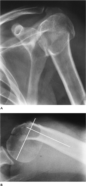
FIGURE 7-2 AP (A) and axillary (B) views of a comminuted impacted proximal humeral fracture. The fracture is angulated (lines) greater than 45 degrees.
|
P.444
 |
|
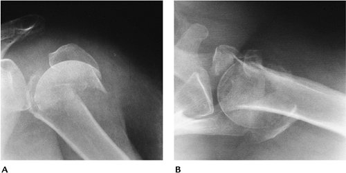
FIGURE 7-3 Four-part fracture with marked displacement of the fragments. The patient was treated with a shoulder prosthesis. AP (A) and axillary (B) views.
|
Suggested Reading
Berquist TH, De Orio JK. The shoulder. In: Berquist TH, ed. Imaging atlas of orthopedic appliances and prostheses. New York, Raven Press; 1995:661–727.
Neer CS II. Displaced proximal humeral fractures. Part I: Classification and evaluation. J Bone Joint Surg 1970;52A:1077–1089.
P.445
Fractures/Dislocations: Glenohumeral Dislocations
Key Facts
-
Dislocations of the glenohumeral joint are the most common dislocation (50% of all dislocations).
-
Dislocations may be anterior (96%), posterior (2%–4%), or less frequently superior or inferior.
-
Anterior dislocations usually are the result of falls with the arm abducted and externally rotated.
-
The humeral head frequently is impacted
against the labrum, resulting in a posterolateral impaction fracture
(67%–76%) or Hill-Sachs lesion. -
The anterior inferior labrum or glenoid also may be injured in 50% (Bankart lesion).
-
Most anterior dislocations are obvious on routine radiographs.
-
-
Posterior dislocations occur with
seizures, shock therapy, or falls with the arm abducted and internally
rotated. The patient’s arm is internally rotated, and external rotation
is blocked.-
Radiographic features may be subtle.
-
Humeral head fixed in internal rotation (100%)
-
Joint may appear widened
-
Overlap of humeral head and glenoid absent or distorted
-
“Trough line” in humeral head caused by anteromedial impaction fracture
-
Lesser tuberosity fracture (25%)
-
Scapular “Y” view makes diagnosis most obvious.
-
Treatment of dislocations is closed reduction unless there are significant associated fractures.
-
-
-
Complications of dislocations:
-
Associated fractures: lesser tuberosity, coracoid, greater tuberosity, subscapularis avulsion
-
Recurrent dislocation
-
Degenerative arthritis
-
Neurovascular injury
-
P.446
 |
|
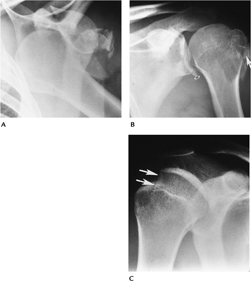
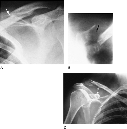
FIGURE 7-4 Anterior dislocations. (A) AP radiograph shows an anterior dislocation with fracture fragments laterally. (B) AP postreduction radiograph shows the tuberosity fracture (arrow) and Bankart lesion (open arrow) adjacent to the inferior glenoid. (C) AP radiograph demonstrates an impaction fracture (arrows) or Hill-Sachs lesion in a patient with a prior dislocation.
|
P.447
 |
|
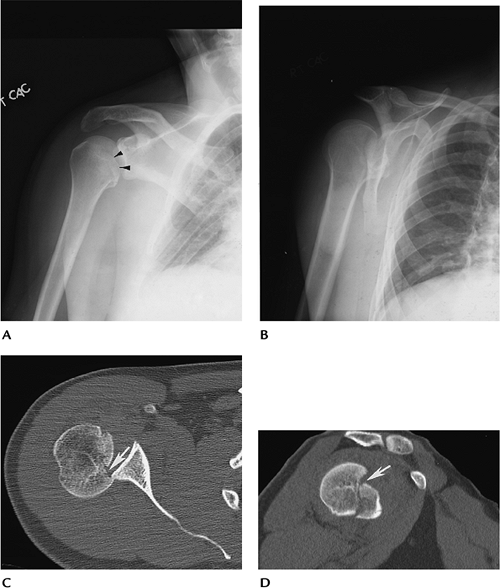
FIGURE 7-5 Posterior dislocations. (A) AP radiograph showing overlap of the glenoid and humeral head with an anteromedial impaction fracture (arrowheads). The humerus is fixed in internal rotation. (B) Scapular “Y” view clearly showing the posterior dislocation of the humeral head. Axial (C) and sagittal (D) CT images demonstrate the position of the head and the humeral head fracture (arrow).
|
Suggested Reading
Robinson M, Aderinto J. Recurrent posterior shoulder instability. J Bone Joint Surg 2005;87A:883–892.
Turkel SJ, Pinto MW, Marshall JL, et al. Stabilizing mechanisms preventing anterior dislocation of the glenohumeral joint. J Bone Joint Surg 1981;63A:1208–1217.
P.448
Fractures/Dislocations: Acromioclavicular Dislocation
Key Facts
-
Dislocations of the acromioclavicular (AC) joint (12%) are less common than glenohumeral (85%) shoulder dislocations.
-
The injury usually is the result of a fall striking the point (AC joint region) of the shoulder.
-
Injuries may be partial or complete (Table 7-3).
-
Routine clavicle radiographs may be
normal with incomplete ligament injury. Weight-bearing views are useful
to classify injuries (Types I and II). -
Closed reduction usually is used for Type
I and II injuries. Internal fixation frequently is required for Type
III to VI lesions.
|
TABLE 7-3 ACROMIOCLAVICULAR DISLOCATIONS
|
||||||||||||
|---|---|---|---|---|---|---|---|---|---|---|---|---|
|
P.449
 |
|
FIGURE 7-6
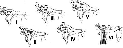
Acromioclavicular joint injuries. Type I: AC sprain, few fibers torn. Type II: disruption of the acromioclavicular ligaments with coracoclavicular ligaments intact. Type III: disruption of the AC and coracoclavicular ligaments. Type IV: disruption of both ligament complexes with posterior clavicular displacement. Type V: disruption of both ligament complexes with marked superior clavicular displacement. Type VI: disruption of the ligament complexes with anterior entrapment beneath the coracoid. |
Fractures/Dislocations: Acromioclavicular Dislocation
P.450
 |
|
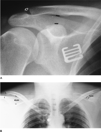
FIGURE 7-7 AC separation. (A) Normal coracoclavicular distance (lines) and slight AC joint widening (open arrow). (B) Weight-bearing stress view of both shoulders showing a coracoclavicular distance of 4 cm and a complete (Type III) separation (right). Note the normal relationship (left).
|
Suggested Reading
Allman FL. Fractures and ligamentous injuries of the clavicle and its articulations. J Bone Joint Surg 1967;49A:774–784.
P.451
Fractures/Dislocations: Sternoclavicular Dislocations
Key Facts
-
Dislocations of the sternoclavicular joint are uncommon (3% of shoulder dislocations).
-
Injury usually occurs with indirect
shoulder trauma. Anterior dislocation is the result of posterolateral
forces transmitted medially. Posterior dislocation is the result of
direct anterior trauma. Almost all (>90%) dislocations are anterior. -
Radiographic evaluation is difficult with
routine views because of bone overlap. CT is the technique of choice to
evaluate the sternoclavicular joint. -
Treatment usually is conservative.
-
Complications are most common with posterior dislocations: tracheal rupture, arch vessel laceration, neural injury.
 |
|
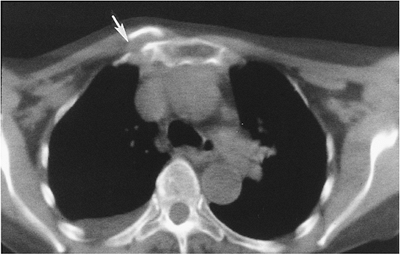
FIGURE 7-8 Axial CT image of an anterior sternoclavicular fracture dislocation (arrow).
|
Suggested Reading
Nettles JL, Linsheid R. Sternoclavicular dislocations. J Trauma 1968;8:158–164.
P.452
Fractures/Dislocations: Clavicle Fractures
Key Facts
-
Clavicle fractures are especially common in children.
-
Injury occurs after a fall on the outstretched hand.
-
Fractures most commonly involve the middle third (80%). The distal clavicle is involved in 15% and medial clavicle in 5%.
-
Routine AP radiographs usually are adequate for diagnosis.
-
Most clavicle fractures can be treated
with closed reduction. Distal fractures involving the AC joint and
ligaments may require internal fixation. -
Complications include malunion, nonunion (1%–2%), and degenerative arthritis when there is joint involvement.
 |
|
FIGURE 7-9 (A) AP radiograph of a minimally displaced fracture of the mid-clavicle (arrow). (B) AP tomogram of a medial clavicular fracture. (C) AP radiograph of a distal clavicular fracture with coracoclavicular ligament disruption (double arrow).
|
Suggested Reading
Neviaser JS. The treatment of fractures of the clavicle. Surg Clin North Am 1963;43:1555–1563.
P.453
Fractures/Dislocations: Posttraumatic Osteolysis
Key Facts
-
Posttraumatic osteolysis occurs in the distal clavicle.
-
Patients present with pain and weakness.
-
Differential diagnosis includes rotator cuff tear and AC separation.
-
Routine radiographs may be normal early,
but later erosive changes occur in the distal clavicle. MRI shows edema
(increased signal on T2-weighted images) in the distal clavicle and
joint. -
When conservative therapy fails, the distal clavicle can be resected.
P.454
 |
|
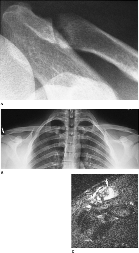
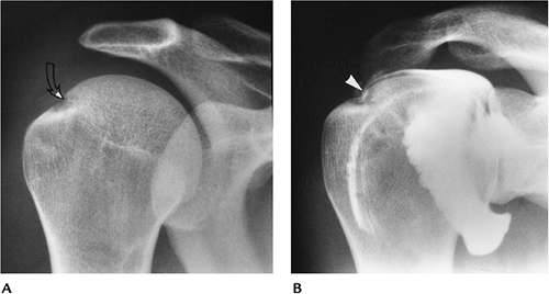
FIGURE 7-10 (A) AP radiograph shows widening of the AC joint with irregularity of the distal clavicle. (B) Stress views of the AC joints show irregularity (arrow) with no displacement. (C) T2-weighted MR image shows increased signal intensity in the distal clavicle (arrow) as the result of edema.
|
Suggested Reading
Quinn SF, Glass TA. Posttraumatic osteolysis of the clavicle. South Med J 1983;76:307.
P.455
Fractures/Dislocations: Scapular Fractures
Key Facts
-
Fractures of the scapula are uncommon (1% of all skeletal fractures).
-
Injury is the result of direct trauma.
-
Scapular fractures can be overlooked on AP and lateral radiographs.
-
Associated fractures of the clavicle and ribs occur in 88%.
-
Articular involvement is best evaluated with CT.
-
Conservative therapy usually is preferred unless there is significant articular deformity or displacement.
P.456
 |
|
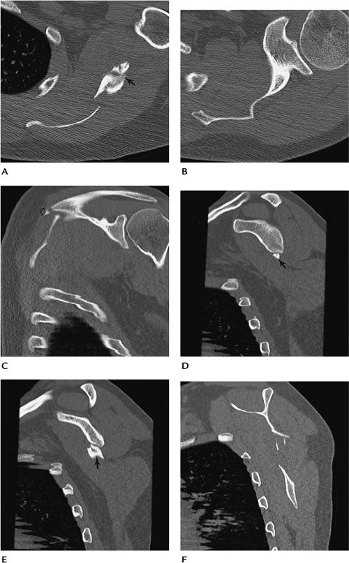
FIGURE 7-11 Scapular fracture. Axial (A,B), coronal (C), and sagittal (D–F) CT images demonstrate a fracture of the scapular wing involving the spine (open arrow) and glenoid neck (arrow), but sparing the articular surface.
|
P.457
Suggested Reading
Rowe CR. Fractures of the scapula. Surg Clin North Am 1963;43:1565–1571.
P.458
Fracture/Dislocations: Humeral Shaft Fractures
Key Facts
-
Humeral shaft fractures account for 1% of all fractures.
-
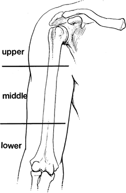
Location of the fracture in relation to
muscle attachments affects the direction of displacement. Proximal
third fractures displace medially because of pectoral muscle forces.
Fractures distal to the deltoid insertion are abducted by the deltoid
muscle. -
Sixty-nine percent of fractures involve the midshaft.
-
Fractures at the mid/distal third junction are difficult to manage. Radial nerve and nutrient artery injury may occur.
-
Complication of humeral shaft fractures
include nonunion, malunion, infection, radial nerve injury (5%–10%),
and compartment syndrome.
 |
|
FIGURE 7-12 Fractures of the humerus are described by location as upper, middle, or lower third.
|
P.459
 |
|
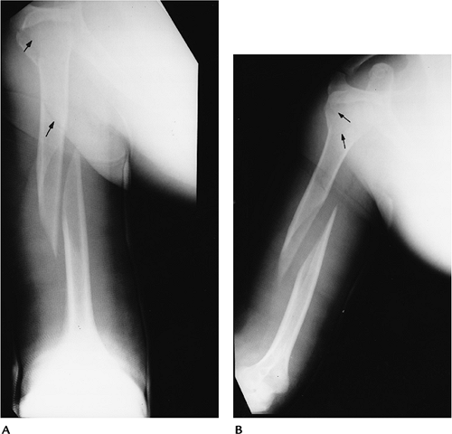
FIGURE 7-13
Two views of the right humerus in a hanging cast demonstrate a displaced spiral fracture of the middle third with overriding and separation of the fragments. This can result in soft tissue interposition and nonunion. There is also an undisplaced fracture of the proximal third of the humerus and tuberosity (arrows). |
Suggested Reading
Berquist TH, Broderson MP. Humeral shaft. In: Berquist TH, ed. Imaging atlas of orthopedic appliances and prostheses. New York: Raven Press; 1995:729–750.
Kleinerman L. Fractures of the shaft of the humerus. J Bone Joint Surg 1966;48B:105–111.
P.460
Rotator Cuff Disease: Basic Concepts
Key Facts
-
The rotator cuff is composed of the supraspinatus, infraspinatus, teres minor, and subscapularis tendons.
-
The rotator cuff is responsible for up to 50% of muscle effort for abduction and 80% for external rotation.
-
Cause of rotator cuff tear (Table 7-4)
most commonly is impingement of the cuff between the coracoacromial
arch and humeral head. Vascular insufficiency may play a role. Chronic
sports trauma and occupational overuse may result in cuff tears. Acute
trauma is an infrequent cause of isolated rotator cuff tears. -
Imaging of rotator cuff disease can be
accomplished with routine radiographs, ultrasound, conventional or CT
arthrography, and conventional MRI or MR arthrography. MRI and MR
arthrography are the techniques of choice at most institutions.
|
TABLE 7-4 ETIOLOGY OF ROTATOR CUFF TEARS
|
||
|---|---|---|
|
P.461
 |
|
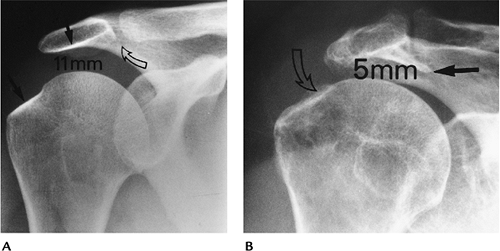
FIGURE 7-14 (A) Normal AP shoulder radiograph with 11-mm humeroacromial distance, normal greater tuberosity, and acromion (black arrows), and no abnormalities in the AC joint (curved open arrow). (B)
AP radiograph in a patient with a chronic rotator cuff tear. The humeroacromial space is 5 mm (normal >7 mm). There is a prominent subacromial osteophyte (black arrow) causing impingement and bony irregularity (open curved arrow) in the greater tuberosity. |
Suggested Reading
Balick
SM, Shelsy RC, Brown TR, et al. MR imaging of the rotator cuff tendon:
Inter-observer agreement and analysis of interpretive errors. Radiology 1997;204:191–194.
SM, Shelsy RC, Brown TR, et al. MR imaging of the rotator cuff tendon:
Inter-observer agreement and analysis of interpretive errors. Radiology 1997;204:191–194.
Zlatkin MB. MRI of the shoulder. Philadelphia: Lippincott Williams & Wilkins; 2003.
P.462
Rotator Cuff Disease: Impingement
Key Facts
-
Ninety-five percent of rotator cuff tears are attributed to chronic impingement.
-
Impingement is the result of anomalies or
abnormalities in the coracoacromial arch (clavicle, anterior acromion,
coracoacromial ligaments, and coracoid). -
Abnormalities may be osseous or soft tissue:
-
Os acromiale
-
Hooked acromion
-
Subacromial osteophytes
-
Soft tissue masses (ganglion cysts)
-
Thickened coracoacromial ligament
-
-
Acromial shape has been classified as
straight (Type 1), curved (Type 2), hooked (Type 3), convex inferior
surface (Type 4), or downward sloping. The scapular Y view may be
superior to MRI for classification of the shape. -
Features of impingement may be identified on routine radiographs, ultrasound, CT, and MRI.
 |
|
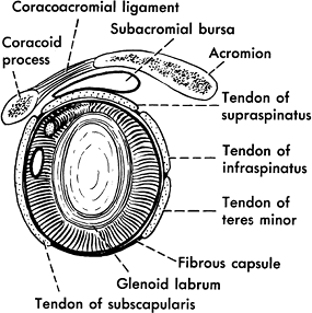
FIGURE 7-15
Sagittal illustration demonstrating the capsule, labrum, and coracoacromial arch (coracoid, coracoacromial ligament, and acromion). |
P.463
 |
|
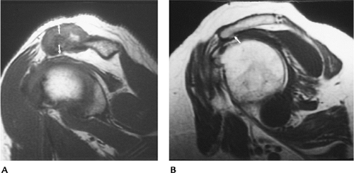
FIGURE 7-16 Impingement syndrome. (A) Sagittal T1-weighted MR image showing hypertrophy of the AC joint (arrows) reducing the humeroacromial space. (B) Sagittal T1-weighted MR image showing an anteriorly angulated acromion with an inferior osteophyte (arrow) causing impingement.
|
Suggested Reading
Mayerhoefer
ME, Breitenseher MJ, Roposch, et al. Comparison of MRI and conventional
radiography for assessment of acromial shape. AJR Am J Roentgenol 2004;184:671–675.
ME, Breitenseher MJ, Roposch, et al. Comparison of MRI and conventional
radiography for assessment of acromial shape. AJR Am J Roentgenol 2004;184:671–675.
Neer CS II. Impingement lesions. Clin Orthop 1983;173:70–77.
P.464
Rotator Cuff Disease: Rotator Cuff Tears—Complete
Key Facts
-
Patients with rotator cuff tears present
with chronic pain. Pain is increased with forward flexion and
abduction. Night pain that prevents sleep is common. Reduced strength
and crepitation may be evident on physical examination. -
Imaging of complete rotator cuff tears
can be accomplished with conventional or CT arthrography, MRI, or MR
arthrography and ultrasound. The size of the tear and tendon morphology
are important to document (≤1 cm = small; 1–3 cm = moderate; 3–5 cm =
large; >5 cm = massive). -
Ultrasound features:
-
Disruption (anechoic) separating tendon ends
-
Volume loss with flattening or concavity of echogenic subdeltoid fat
-
Subdeltoid bursa fluid
-
Irregularity of greater tuberosity
-
-
Arthrography:
-
Contrast media extends through torn segment into subacromial subdeltoid bursa
-
Size measured on AP and scapular “Y” views
-
-
MRI features:
-
Increased signal intensity on T2-weighted
image involving full thickness. Signal intensity increased from proton
density to T2-weighted sequence. -
Tendon retraction or muscle atrophy may be present.
-
Size measured on axial, sagittal, and coronal images.
-
Fluid (increased signal on T2-weighted sequence) is present in subacromial-subdeltoid bursa.
-
-
Treatment most commonly is surgical repair.
P.465
 |
|
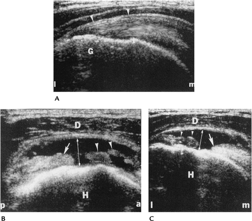
FIGURE 7-17 Ultrasound of the rotator cuff. (A) Longitudinal sonogram in a healthy patient shows the echo texture of the supraspinatus (arrowheads). G = greater tuberosity, l = lateral, m = medial. Longitudinal (B) and transverse (C) images in a patient with a large tear from the articular surface to the bursal surface (double arrow). Note the retraction (arrow) of the proximal tendon and debris (arrowheads) within the defect. H = humeral head, D = deltoid, m = medial, l = lateral, a = anterior, p = posterior. (From
Lin J, Jacobson JA, Fessell DP, et al. An illustration tutorial of musculoskeletal sonography. Part II: upper extremity. AJR Am J Roentgenol 2000;175:1071–1079.
) |
P.466
P.467
 |
|
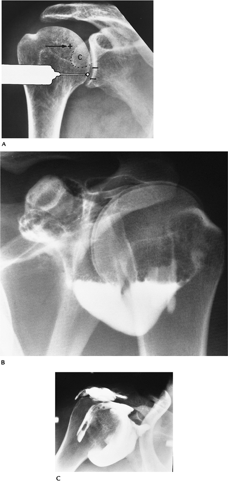
FIGURE 7-18 Arthrography. (A) Usual anterior entry site for shoulder arthrography and the rotator cuff interval entry site (+). (B) Normal double-contrast arthrogram with no air or contrast in the subacromial bursa. (C) Single-contrast arthrogram with contrast in the tear and subacromial bursa.
|
P.468
 |
|
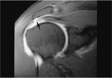
FIGURE 7-19 Coronal MR arthrogram image of a moderate-sized full-thickness rotator cuff tear with retraction (arrow).
|
Suggested Reading
Carrino JA, McCauley TR, Katz LD, et al. Rotator cuff: Evaluation with fast spin-echo versus conventional spin-echo imaging. Radiology 1997;202:533–539.
Depelteau
H, Bureau NJ, Cardinal E, et al. Arthrography of the shoulder: A simple
fluoroscopically guided approach to target the rotator cuff interval. AJR Am J Roentgenol 2004;182:329–332.
H, Bureau NJ, Cardinal E, et al. Arthrography of the shoulder: A simple
fluoroscopically guided approach to target the rotator cuff interval. AJR Am J Roentgenol 2004;182:329–332.
Lin J, Jacobson JA, Fessell DP, et al. An illustrated tutorial of musculoskeletal sonography: Part 2, upper extremity. AJR Am J Roentgenol 2000;175:1071–1079.
P.469
Rotator Cuff Disease: Partial Tears
Key Facts
-
Partial tears of the rotator cuff may
involve the superior (bursal) (28%), inferior (articular) surface
(33%), both surfaces (39%), or midsubstance. Tears involve only a
portion of the tendon thickness. Arthroscopic classification for
partial tears is grade 1 if less than 25% of the fibers are involved,
grade 2 if less than 50% of the fibers are involved, and grade 3 if
more than 50% of fibers are involved. -
It is not unusual for partial tears to be asymptomatic in patients more than 60 years of age.
-
Partial tears can be evaluated with ultrasound, arthrography, conventional MRI, or MR arthrography.
-
MR arthrography is most accurate for evaluating partial tears and associated abnormalities, such as impingement.
-
Conventional MRI is 94% specific and 89%
accurate for full-thickness tears, but only 69% specific and 84%
accurate for partial tears.
P.470
 |
|
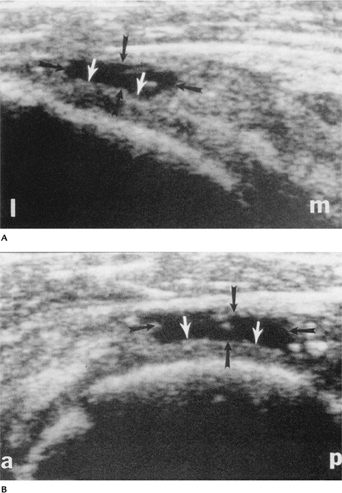
FIGURE 7-20 Ultrasound in a 67-year-old man with a partial tear of the rotator cuff. Longitudinal (A) and transverse (B) images showing a bursal surface tear (black arrows) and intact fibers (white arrows). a = anterior; l = lateral; m = medial; p = posterior. (From
Lin J, Jacobson JA, Fessell DP, et al. An illustrated tutorial of musculoskeletal sonography: Part 2, upper extremity. AJR Am J Roentgenol 2000;175:1071–1079.
) |
P.471
 |
|
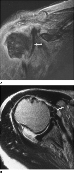
FIGURE 7-21 Arthrogram of a partial cuff tear. (A) Routine radiograph showing an erosion (curved arrow) near the greater tuberosity. (B) Arthrogram showing a linear collection of contrast (arrowhead) without communication with the subacromial bursa.
|
 |
|
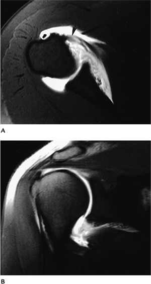
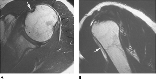
FIGURE 7-22 Sagittal MR arthrogram with T1-weighted sequence showing a large partial tear (arrow).
|
Suggested Reading
Evanto AM, Stiles RG, Fajman WA, et al. MR imaging diagnosis of rotator cuff tears. AJR Am J Roentgenol 1988;151:751–754.
P.472
Lin J, Jacobson JA, Fessell DP, et al. An illustrated tutorial of musculoskeletal sonography: Part 2, upper extremity. AJR Am J Roentgenol 2000;175:1071–1079.
Meister
K, Thesing J, Montgomery WJ, et al. MR arthrograph of partial tears of
the undersurface of the rotator cuff: An arthroscopic correlation. Skel Radiol 2004;33:136–141.
K, Thesing J, Montgomery WJ, et al. MR arthrograph of partial tears of
the undersurface of the rotator cuff: An arthroscopic correlation. Skel Radiol 2004;33:136–141.
P.473
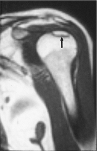
Rotator Cuff Disease: Tendinitis/Tendinosis
Key Facts
-
Tendinosis is common with aging and related to mucoid degeneration in the tendons.
-
Tendon degeneration shows thickening with
heterogeneous echo texture on ultrasound. There is increased signal
intensity on proton density MR images that does not increase in signal
intensity on T2-weighted images. -
Tendon inflammation may be difficult to differentiate from tendinosis on MR images.
P.474
 |
|
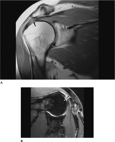
FIGURE 7-23 Tendinosis. Coronal proton density (A) image shows an area of increased signal intensity in the supraspinatus (arrow). Fast spin-echo T2-weighted MR image with fat suppression (B) shows a focal articular surface partial tear (white arrowhead) with adjacent tendinosis (black arrow). Note the marked hypertrophy of the AC joint (large white arrow).
|
Suggested Reading
Kjellin
I, Ho CP, Cervilla V, et al. Alterations in supraspinatus tendon at MR
imaging. Correlation with histologic findings in cadavers. Radiology 1991;181:837–841.
I, Ho CP, Cervilla V, et al. Alterations in supraspinatus tendon at MR
imaging. Correlation with histologic findings in cadavers. Radiology 1991;181:837–841.
P.475
Rotator Cuff Disease: Postoperative Changes
Key Facts
-
Rotator cuff repairs may be accomplished with open techniques or arthroscopy.
-
Resection of the distal clavicle and a portion of the acromion may be required to relieve impingement.
-
Up to 26% of patients have recurrent symptoms after repair.
-
Complications seen after cuff repair include
-
Recurrent rotator cuff tear
-
Impingement
-
Bursitis
-
Tendinitis
-
Suprascapular nerve palsy
-
Adhesive capsulitis
-
Deltoid muscle dehiscence
-
Scarring
-
Biceps tendon subluxation
-
-
Postoperative imaging can be difficult because small leaks can be defined arthrographically that mimic tears.
-
Ultrasound may accurately define
recurrent tears. However, MRI, specifically MR arthrography, is best
suited to evaluate complications.
P.476
 |
|
FIGURE 7-24 AP radiograph of an arthrogram demonstrating a recurrent tear with contrast in the subdeltoid bursa (arrows). Note the resected clavicle (large arrow).
|
P.477
 |
|
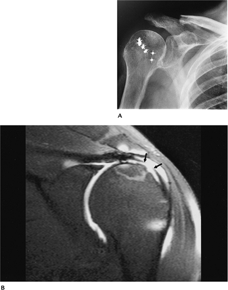
FIGURE 7-25 (A) Routine radiograph after rotator cuff repairs with resection of the distal clavicle and soft tissue anchors in the humerus. (B) Coronal fast spin-echo fat-suppressed T2-weighted MR arthrogram image shows a recurrent tear (arrows).
|
Suggested Reading
Rand T, Trattnig S, Breitenseher M, et al. The postoperative shoulder. Top Magn Reson Imaging 1999;10:203–213.
Steinbach LS, Palmer WE, Schweitzer ME. MR arthrography. Radiographics 2002;22:1223–1246.
P.478
Instability: Basic Concepts
Key Facts
-
Shoulder stability depends on an intact capsule, labrum, pericapsular soft tissues, and glenohumeral osseous structures.
-
Instability may be anterior (>90%), posterior (5%), or multidirectional.
-
Anterior stability depends on the
capsule, three glenohumeral ligaments (superior, middle, and inferior),
anterior labrum, and subscapularis. -
Posterior stability is maintained by the capsule, posterior labrum, and rotator cuff muscles.
-
Instability can be categorized into four types:
Type I Involuntary unidirectional (usually anterior) instability caused by trauma Type II Overuse or repetitive trauma in throwing athletes and swimmers Type III Multidirectional instability caused by generalized ligament laxity Type IV Voluntary instability
Suggested Reading
Iannotti JP, Gabriel JP, Schneck SL, et al. The normal glenohumeral relationship. J Bone Joint Surg 1992;74A:491–500.
P.479
Instability: Recurrent Subluxation/Dislocations—Capsular Abnormalities
Key Facts
-
Recurrent anterior dislocation is reported in 50% to 90% of patients after anterior dislocation.
-
Hill-Sachs lesions, Bankart lesions, and associated labral, capsular, and rotator cuff abnormalities are common.
-
The shoulder capsule is categorized into three types:
Type I Capsules attach at the labral margin Type II Capsules attach just medial to the labral margin Type III Capsules attach more than 1 cm medial to the labrum. These patients are more susceptible to anterior subluxation. -
Imaging of capsular abnormalities can be
accomplished with arthrography or MRI. MR arthrography is preferred to
better demarcate the capsule size and attachments.
 |
|
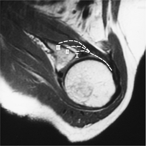
FIGURE 7-26 Axial MR image demonstrating the types of capsular attachment (broken lines): Type I at glenoid margin, Type II just medial to margin, and Type III more than 1 cm beyond the glenoid margin.
|
P.480
 |
|
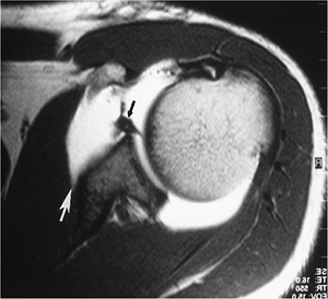
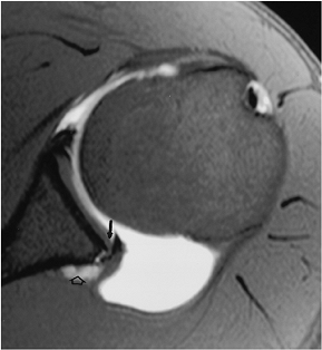
FIGURE 7-27 Axial MR arthrogram image in a patient with prior anterior dislocation. There is stripping of the anterior capsule (white arrow) and a labral tear (black arrow) with a complete subscapularis tear.
|
 |
|
FIGURE 7-28
Multidirectional instability. Stress arthrogram image after prior anterior repair shows inferior subluxation of the humeral head. |
P.481
Suggested Reading
Ly JQ, Beall DP, Sanders JG. MR imaging of glenohumeral instability. AJR Am J Roentgenol 2003;181:203–213.
Moseley
HG, Overgaard B. The anterior capsular mechanism in recurrent anterior
dislocation of the shoulder: Morphological and clinical studies with
special reference to the glenoid labrum and glenohumeral ligaments. J Bone Joint Surg 1962;44:913–927.
HG, Overgaard B. The anterior capsular mechanism in recurrent anterior
dislocation of the shoulder: Morphological and clinical studies with
special reference to the glenoid labrum and glenohumeral ligaments. J Bone Joint Surg 1962;44:913–927.
P.482
Instability: Labral Tears
Key Facts
-
The anterior labrum is triangular and the posterior labrum is slightly rounded in most patients.
-
Labral tears may involve the anterior
inferior labrum (anterior instability) or extend over a larger area,
resulting in multidirectional instability. -
Bankart lesions may be labral or osteochondral in nature. There are also several variants.
-
Perthes lesion: periosteum of the scapula
is stripped but remains in place. The labrum may be detached or remain
in normal position. -
Anterior labroligamentous periosteal
sleeve avulsion: periosteum is stripped, resulting in rotation of
labroligamentous structures.
-
-
Superior labral lesions also may involve
the biceps tendon. Superior labral lesions are called superior labrum
anterior posterior (SLAP) lesions because of the extension into the
anterior and posterior labrum. -
SLAP lesions are divided into 10 types, but the four types initially described are still most commonly used:
Type I Localized tears or fraying at junction of biceps tendon Type II Tear extends anteriorly and posteriorly Type III Tear with a bucket-handle configuration Type IV Tear extends into biceps tendon -
SLAP lesions are associated with rotator cuff tears and instability in 15% to 25% of patients.
-
Imaging of labral injuries and the
capsule can be accomplished with CT, conventional arthrography, or MRI.
MR arthrography is the optimal technique.
P.483
 |
|
FIGURE 7-29
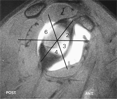
Sagittal MR arthrogram demonstrating the six labral quadrants: 1, superior; 2, anterior superior; 3, anterior inferior; 4, inferior; 5, posterior inferior; 6, posterior superior. Most unstable injuries occur in segment 3. The lesions may also be described like the face of a clock. |
P.484
 |
|
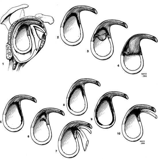
FIGURE 7-30
Categories of SLAP lesions: 1, fraying of the superior labrum; 2, stripping of the superior labrum and biceps tendon from the glenoid; 3, bucket-handle tear of the labrum and intact biceps tendon; 4, bucket-handle tear extending into the biceps tendon; 5, Bankart with superior extension to include the superior labrum and biceps tendon; 6, anterior and posterior flap tear with superior biceps involvement; 7, biceps labral complex tear with extension into the middle glenohumeral ligament; 8, superior labral tear with posterior extension; 9, nearly complete labral detachment; 10, SLAP with extension of the tear to the rotator interval and involved structures. |
P.485
 |
|
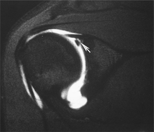
FIGURE 7-31 Axial MR arthrogram image demonstrating an anterior labral tear (arrow).
|
 |
|
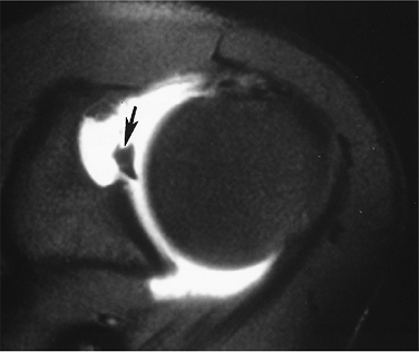
FIGURE 7-32 Coronal fat-suppressed arthrogram image demonstrating a Type 3 SLAP tear (arrow).
|
P.486
 |
|
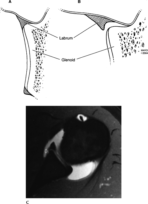
FIGURE 7-33 Perthes lesion. Normal labrum and its insertion (A) and the Perthes lesion (B). Axial MR arthrogram image showing the stripped periosteum (open arrow) and contrast extending under the labrum though position is anatomic.
|
P.487
Suggested Reading
Hunter JC, Blatz, DJ, Escobedo EM. SLAP lesions of the glenoid labrum: CT arthrographic and arthroscopic correlation. Radiology 1992;184:513–518.
Maesenees
MD, Van Roy F, Lenchek L, et al. CT and MR arthrography of the normal
and pathologic interior superior labrum and labral-bicipital complex. Radiographics 2000;20:567–581.
MD, Van Roy F, Lenchek L, et al. CT and MR arthrography of the normal
and pathologic interior superior labrum and labral-bicipital complex. Radiographics 2000;20:567–581.
Tuite
MJ, Cirillo RL, DeSmet AA, et al. Superior labral anterior posterior
tears: Evaluation of three MR signs on T2-weighted sequences. Radiology 2003;215:841–845.
MJ, Cirillo RL, DeSmet AA, et al. Superior labral anterior posterior
tears: Evaluation of three MR signs on T2-weighted sequences. Radiology 2003;215:841–845.
P.488
Instability: Humeral Osteochondral Or Ligament Avulsions
Key Facts
-
Avulsion of the glenohumeral ligament may
involve soft tissue (humeral avulsion of glenohumeral ligament) or bony
(bony humeral avulsion of glenohumeral ligament) avulsion. -
Lesions are seen in 7.5% to 9.4% of patients with anterior instability.
-
Prior anterior dislocations are evident in 67% of patients.
-
Rotator cuff tears and fractures may be associated.
-
MR images may show thickening or irregularity of the glenohumeral ligament.
-
MR arthrograms demonstrate extravasation at the humeral attachment and capsular stripping.
P.489
 |
|
FIGURE 7-34 Humeral avulsion of glenohumeral ligament lesion. Axial (A) and coronal (B) MR arthrogram images demonstrate anterior inferior capsular avulsion with a subscapularis tendon tear (arrow).
|
Suggested Reading
Bui-Mansfield
LT, Taylor DC, Uhorchak JM, et al. Humeral avulsion of the glenohumeral
ligament: Imaging features and review of the literature. AJR Am J Roentgenol 2002;179:649–655.
LT, Taylor DC, Uhorchak JM, et al. Humeral avulsion of the glenohumeral
ligament: Imaging features and review of the literature. AJR Am J Roentgenol 2002;179:649–655.
P.490
Instability: Posterior Instability
Key Facts
-
Posterior dislocations account for 2% to 4% of dislocations.
-
Recurrent subluxation is common in throwing athletes in patients with repetitive microtrauma.
-
Posterior labrocapsular sleeve avulsion has also been described as a cause of posterior instability.
-
Bennett lesion-posterior labral injury with calcification/ossification at the posterior-inferior glenoid margin.
-
MR arthrography is the technique of
choice for evaluating posterior instability. Bennett lesions may be
more easily identified with CT.
 |
|
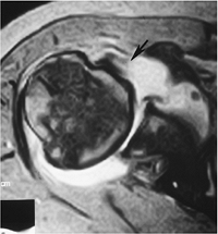
FIGURE 7-35 Axial MR arthrogram image demonstrating a large posterior capsule with glenolabral separation (arrow) and a small paralabral cyst (open arrow).
|
Suggested Reading
Ferrari
DJ, Ferrari DA, Coumas J, et al. Posterior ossification of the
shoulder: Posterior ossification of the shoulder: The Bennett
lesion-etiology, diagnosis, and treatment. Am J Sports Med 1994;22:171–176.
DJ, Ferrari DA, Coumas J, et al. Posterior ossification of the
shoulder: Posterior ossification of the shoulder: The Bennett
lesion-etiology, diagnosis, and treatment. Am J Sports Med 1994;22:171–176.
Yu JS, Ashman OJ, Jones G. The POLPSA lesion: MR arthrography and clinical correlation in 17 patients. Skel Radiol 2002;31;396–399.
P.491
Instability: Multidirectional Instability
Key Facts
-
Multidirectional instability typically is atraumatic and accounts for 2% of cases of instability.
-
Instability may be anterior and posterior or inferior and superior.
-
Multidirectional instability occurs with labrocapsular laxity in segments 3 to 5 (Fig. 7-29).
-
SLAP lesions may also be evident.
 |
|
FIGURE 7-36
Multidirectional instability. Axial MR arthrogram image demonstrates anterior and posterior capsular enlargement with posterior humeral subluxation. There is a subscapularis tendon tear (arrow). |
Suggested Reading
Fischbach TJ, Seeger LL. Magnetic resonance imaging of glenohumeral instability. Top Magn Reson Imaging 1994;6:121–132.
P.492
Instability: Labral Variants
Key Facts
-
The normal labrum is triangular. However, the posterior labrum may appear more rounded.
-
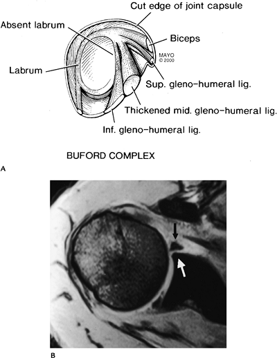
The anterior superior labrum may be
absent with associated thickening of the middle glenohumeral ligament.
This anatomic variant is called a Buford complex. -
A sublabral foramen (focal detachment
anterosuperiorly) is present in 8% to 12% of patients. The middle
glenohumeral ligament is not thickened in this case.
P.493
 |
|
FIGURE 7-37 (A) Buford complex with absent anterosuperior labrum and thickening of the middle glenohumeral ligament. (B) Axial MR image demonstrates an absent labrum (white arrow) and thickened middle glenohumeral ligament (black arrow).
|
Suggested Reading
Neumann CH, Petersen SA, Jahnke AH. MR imaging of the labral-capsular complex: Normal variations. AJR Am J Roentgenol 1991;157:1015–1021.
Tuite
MJ, Blankenbaker DG, Siefert M, et al. Sublabral foramen and Buford
complex: Inferior extent of the unattached or absent labrum in 50
patients. Radiology 2002;223:137–142.
MJ, Blankenbaker DG, Siefert M, et al. Sublabral foramen and Buford
complex: Inferior extent of the unattached or absent labrum in 50
patients. Radiology 2002;223:137–142.
P.494
Biceps Tendon
Key Facts
-
The biceps muscle has two bellies. The
tendon of short head attaches to the coracoid. The tendon of the long
head extends over the humeral head and passes through the bicipital
groove hooded by the transverse ligament. -
Biceps tendon abnormalities include
-
Tenosynovitis
-
Subluxation/dislocation
-
Tendon rupture
-
Stenosing tenosynovitis
-
-
Tendinopathy may be the result of
impingement, subluxation, or attrition. The latter is caused by
inflammation in the groove leading to stenosis, osteophyte formation,
or tendon thinning. -
Tendon rupture most commonly occurs proximally (96%).
-
Imaging of the osseous groove and tendon
can be accomplished with CT, arthrography, MRI, or ultrasound. Images
in the axial plane are most useful for evaluating the bicipital groove
and tendon.
 |
|
FIGURE 7-38 Axial (A) and coronal (B) MR arthrogram images showing the normal course and low signal intensity of the long head of the biceps tendon (arrows).
|
P.495
P.496
 |
|
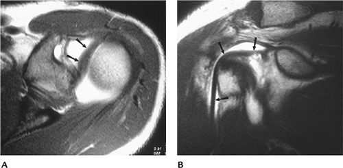
FIGURE 7-39 Coronal (A) axial (B) MR images in a patient with a subscapularis tear and dislocation of the biceps tendon (arrow).
|
P.497
 |
|
FIGURE 7-40 Axial T1-weighted (A) and sagittal T2-weighted image (B) showing a thinned atrophic biceps tendon (arrow).
|
Suggested Reading
Tuckman GA. Abnormalities of the long head of the biceps tendon of the shoulder. MR image findings. AJR Am J Roentgenol 1994;163:1183–1188.
P.498
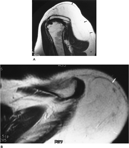
Adhesive Capsulitis
Key Facts
-
Adhesive capsulitis (frozen shoulder) may develop after trauma or present as an idiopathic condition.
-
Idiopathic adhesive capsulitis is most common in the nondominant shoulder of middle-aged or older females.
-
The condition is bilateral in 34%.
-
Patients present with pain and reduced motion.
-
Imaging of capsulitis requires evaluating
capsular volume (normal >10 mL); therefore, contrast should be
injected and the volume injected should be documented. This can be done
with conventional or CT arthrography or MR arthrography. Conventional
MRI is not as useful compared with these techniques. -
Distention arthrography (gradual increased pressure and volume injected) is useful in mild to moderately severe cases.
 |
|
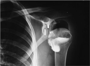
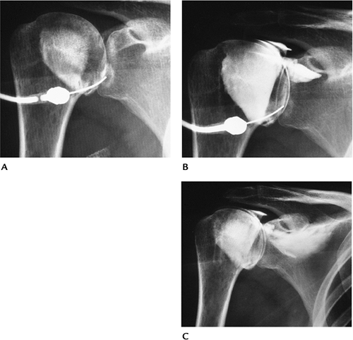
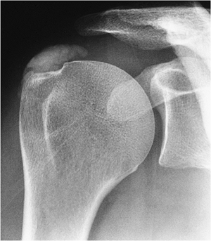
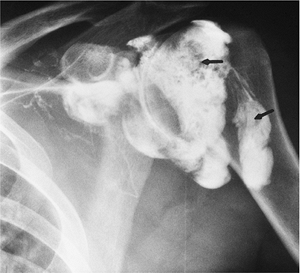
FIGURE 7-41 Female with adhesive capsulitis treated with distention arthrography. (A) Initial arthrogram showing a small tight capsule (4 mL injected). (B,C) Increased volumes of contrast mixed with anesthetic showing volume increase (B) and eventual capsular rupture (C), which is the end point of the procedure.
|
P.499
Suggested Reading
Shaffer B, Tibone JE, Kerlan RK. Frozen shoulder. J Bone Joint Surg 1992;74A:738–746.
P.500
Nerve Entrapment Syndromes
Key Facts
-
Neural injury may occur with fractures and dislocations.
-
Nerve compression syndromes may involve
the axillary nerve or branches as it passes between the teres minor and
major (quadrilateral space syndrome) or the suprascapular nerve in the
supraspinous notch or in its course to supply the supraspinatus and
infraspinatus muscles. -
Quadrilateral space syndrome: The
axillary nerve and posterior humeral circumflex artery and vein pass
between the tere minor and tere major in the quadrilateral space. Nerve
compression in this region results in pain, paresthesias, and muscle
atrophy in the teres muscles. Clinical diagnosis is difficult. -
Suprascapular nerve compression: The
suprascapular nerve has motor and sensory fibers. The nerve enters the
supraspinous fossa through the suprascapular notch and passes beneath
the superior transverse scapular ligament. The nerve supplies the
supraspinatus and infraspinatus. Anterior compression affects both
muscles, and posterior compression affects the infraspinatus.
Compression may be secondary to trauma, soft tissue masses, or dilated
veins. Patients present with pain, which may mimic rotator cuff
disease, and muscle atrophy. -
MRI is the technique of choice for
evaluating the neuromuscular structures of the shoulder and excluding
other causes of shoulder pain.
P.501
 |
|
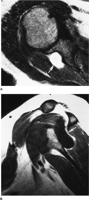
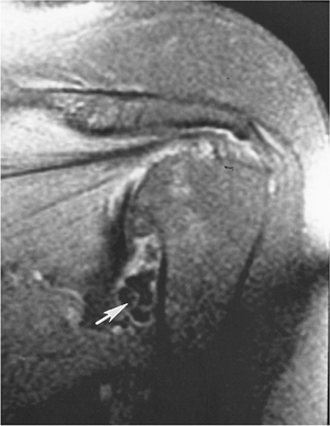
FIGURE 7-42 Axial T2- (A) and sagittal T1-weighted (B) images demonstrating a ganglion cyst (arrow) compressing the suprascapular nerve.
|
P.502
Suggested Reading
Cothran
RL, Helms CA. Quadrilateral space syndrome: Incidence of imaging
findings in a population referred for MRI of the shoulder. AJR Am J Roentgenol 2005;184:989–992.
RL, Helms CA. Quadrilateral space syndrome: Incidence of imaging
findings in a population referred for MRI of the shoulder. AJR Am J Roentgenol 2005;184:989–992.
Fritz RC, Helms CA, Steinbach LS, et al. Suprascapular nerve entrapment: Evaluation with MR imaging. Radiology 1992;182:437–444.
Robinson P, White LM, Lax M, et al. Quadrilateral space syndrome caused by glenoid labral cyst. AJR Am J Roentgenol 2000;175:1103–1105.
P.503
Infection/Inflammatory Arthropathies
Key Facts
-
The shoulder frequently is involved with degenerative and other arthropathies.
-
Early changes may be difficult to detect
on conventional radiographs. MRI or MR arthrography may detect early
synovial and bone changes more clearly. -
Bursal inflammatory changes also may result in shoulder pain.
-
Bursal abnormalities may be detected with
ultrasound or MRI. Routine radiographs may demonstrate calcification in
bursae or peritendinous soft tissues.
 |
|
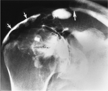
FIGURE 7-43 AP radiograph showing extensive soft tissue calcification caused by peritendinitis.
|
P.504
 |
|
FIGURE 7-44 Arthrogram showing multiple filling defects (arrows) resulting from synovitis.
|
P.505
 |
|
FIGURE 7-45 Coronal fat-suppressed T2-weighted MR image in a patient with degenerative arthritis and multiple loose bodies (arrow).
|
Suggested Reading
Brower AC. Arthritis in black and white. 2nd ed. Philadelphia: WB Saunders; 1997:141–154.
P.506
Osteonecrosis
Key Facts
-
Detection of early osteonecrosis can be difficult with routine radiographs (see Chapter 4 for a more complete discussion).
-
MRI is the technique of choice for detection and classification of early avascular necrosis.
-
MR images in the axial and coronal planes
using T1- and T2-weighted or short T1 inversion recovery sequences is
sufficient for diagnosis. -
A single T1-weighted coronal image may be sufficient for screening.
P.507
 |
|
FIGURE 7-46 T1-weighted coronal image of the shoulder showing a low signal intensity line (arrow) defining the margin of the avascular necrosis.
|
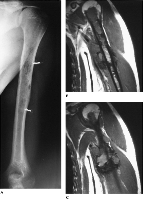
Neoplasms
Key Facts
-
Routine radiographs are essential for
evaluating skeletal neoplasms and may show abnormalities
(calcification, fat, mass) when soft tissue neoplasms are present. -
Soft tissue neoplasms in the shoulder
include lipoma, desmoid tumors (22% involve the shoulder), epithelioid
sarcomas, and alveolar soft part sarcomas. -
MRI is the technique of choice for
evaluating soft tissue masses. T1- and T2-weighted images are
essential. Intravenous gadolinium is used routinely in our practice. -
MRI or CT may be used for staging skeletal neoplasms.
-
Common skeletal lesions are as follows:
| Benign | No. in Shoulder/Total/% in Shoulder |
|---|---|
| Chondroblastoma | 119/25/21% |
| Osteochondroma | 159/872/18% |
| Chondroma | 43/290/15% |
| Giant cell tumor | 22/568/4% |
| Osteoid osteoma | 13/331/4% |
| Hemangioma | 4/108/4% |
| Malignant | No. in shoulder/Total/% in Shoulder |
|---|---|
| Chondrosarcoma | 144/895/16% |
| Ewing sarcoma | 57/512/11% |
| Lymphoma | 70/694/10% |
| Osteosarcoma | 159/1649/10% |
| Fibrosarcoma | 21/255/8% |
| Myeloma | 57/814/7% |
P.508
 |
|
FIGURE 7-47 Lipoma. T1-weighted sagittal (A) and axial (B) images of a large superficial lipoma (arrows).
|
P.509
 |
|
FIGURE 7-48 Malignant fibrous histiocytoma with soft tissue extension. (A) AP radiograph showing a large irregular lytic area in the humerus (arrows). (B,C) Coronal MR images showing the extent of marrow involvement and soft tissue extension.
|
Suggested Reading
Unni KK. Dahlin’s bone tumors: General aspects and data on 11,087 cases. 5th ed. Philadelphia: Lippincott-Raven; 1996.
P.510
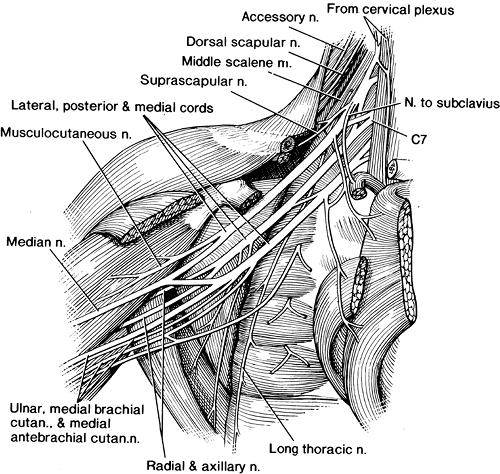
Brachial Plexus
Key Facts
-
The brachial plexus arises from the
anterior rami of the fifth to eighth cervical and first thoracic
nerves. The nerve roots form trunks (upper, middle, and lower) in the
brachial plexus. Each trunk has anterior and posterior divisions. -
The brachial plexus is a difficult area to image using CT or other conventional techniques.
-
The lower neck through the shoulder needs
to be imaged to evaluate the neural structures of the brachial plexus.
This can be accomplished with T1-weighted sagittal and T2-weighted
axial images. -
MRI is useful for evaluating primary or metastatic lesions, trauma, and inflammatory changes involving the brachial plexus.
 |
|
FIGURE 7-49 Anatomic illustration of the brachial plexus.
|
P.511
 |
|
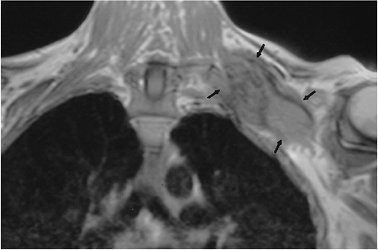
FIGURE 7-50 Metastatic tumor involving the brachial plexus. Coronal T1-weighted image demonstrates a large mass (arrows) encasing the brachial plexus.
|
Suggested Reading
Rapaport S, Blair DN, McCarthy SM, et al. Brachial plexus: Correlation of MR imaging with CT and pathologic findings. Radiology 1988;167:161–165.