
Open Reduction Internal Fixation Using an Extensile Lateral Approach for a Joint Depression Fracture
II – Lower Extremity > 35 – Open Reduction Internal Fixation Using
an Extensile Lateral Approach for a Joint Depression Fracture
(ORIF) of the calcaneus remain controversial. Results after surgery are
superior to nonoperative management outcomes only if the posterior
facet is anatomically reduced and if complications are avoided (1,2,3).
The best indication for internal fixation of the calcaneus is an
intra-articular fracture with displacement of the posterior facet in a
young active patient with no medical problems. Middle-aged patients
should be considered operative candidates based on their lifestyles and
fracture patterns. The more active a patient is, the more likely that
he/she would benefit from properly performed surgery. Even in less
active patients, surgery may improve the functional result if the
fracture displacement produces significant widening or shortening of
the heel, because skeletal distortion increases the chances of a poor
result when the fracture is treated nonoperatively.
patient’s overall health, including mental status, the fracture
pattern, and/or the surgeon’s experience. Relative contraindications to
internal fixation include neuropathy, insulin-dependent diabetes,
peripheral vascular disease, venous stasis or congestion, lymphedema,
immune compromise, and other disorders or behaviors, such as smoking,
that might impede healing. Advanced age is a relative contraindication.
Patient compliance is important in obtaining a good functional result
after surgical intervention and must be considered preoperatively.
Patients with a history of jumping from heights must be carefully
scrutinized for signs of mental illness or depression. When
appropriate, these patients should be evaluated by a mental health
professional.
subset of calcaneal fractures with severe comminution of the posterior
facet are resistant to anatomic reduction and internal
fixation.
In these injuries, primary fusion may be a good alternative to internal
fixation. Less comminuted but complex injuries with multiple fractures
through the posterior facet offer a relative contraindication for
surgeons who do not have significant experience in the operative
treatment of calcaneal fractures.
thorough irrigation and debridement of the traumatic wounds and the
fracture constitute the first priority after resuscitation and trauma
evaluation. If the wound is lateral and allows reduction of the
posterior facet, then it is reduced and fixed with lag screws. This is
performed only after re-prepping and redraping after the debridement.
If the wound is medial, internal fixation is delayed until the
soft-tissue environment has been addressed. Temporary, triangular,
external fixation on the lateral side of the foot and ankle can be used
to maintain the general alignment of the heel until definitive
management is undertaken. The external fixation pins are placed in the
tuberosity, the cuboid, and the talus. Definitive ORIF is performed 2
to 3 weeks after wound closure if the soft tissues are in good
condition.
fracture must include a careful and complete survey of the axial as
well as the appendicular skeleton. Spinal fractures are common in
patients with calcaneal fractures because the mechanism of injury is
often axial loading caused by a fall from a height. X-rays of the
affected extremity and spine should be routine.
surgeon begins the physical examination of the foot and ankle with the
evaluation of the soft tissues. Compartment syndrome of the foot is
difficult to diagnose clinically. Calcaneal fractures are painful but
usually respond to splinting, elevation, ice, and analgesics. Severe
and unrelenting pain should be considered a compartment syndrome until
proven otherwise. Significant swelling in the foot is common after
calcaneal fracture, and the region may not feel tense even in the face
of compartment syndrome. Sensation is rarely affected, and its absence
does not rule out compartment syndrome. Pain on passive extension of
the metatarsophalangeal joints is the best method of clinical
examination but is not sensitive enough to rule out a compartment
syndrome.
most accurate method of diagnosis. Pressures should be taken in the
central (interosseous) and medial compartments. Handheld devices and
arterial line monitors are equally effective in measuring compartment
pressures. We perform a fasciotomy if the compartment pressure is
within 30 mm Hg of the diastolic pressure. If the pressure measurements
are borderline and if significant clinical symptoms are absent, then
the foot may be observed and pressures rechecked in 30- to 60-minute
intervals. If a fasciotomy is required, the calcaneal fracture is not
usually fixed at this time because the incisions necessary for the
fasciotomy are not useful for reduction and fixation of the calcaneus.
and ankle is directed at diagnosing concomitant injuries. Palpation of
the entire lower leg, ankle, and foot may help in identifying such
injuries. Commonly associated regional injuries include ankle fractures
(especially the lateral malleolus), ankle-ligament injury, peroneal
tendon dislocation, mid foot fractures, talar fractures, and metatarsal
fractures. Radiographic evaluation of symptomatic or suspicious areas
is essential.
an injury to the hind foot include anteroposterior (AP), lateral, and
mortise views of the ankle; AP, lateral, and oblique views of the foot;
and an axial view of the calcaneus (Harris view). Contralateral axial
and lateral views of the calcaneus and an oblique view of the
contralateral foot may be useful in delineating the patient’s normal
anatomy. The ankle radiographs are necessary so the surgeon can
rule
out concomitant ankle or talar fractures as well as evaluate the
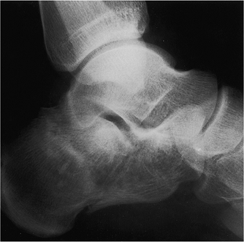
calcaneus, subtalar joint, and calcaneocuboid joint. The lateral view
of the calcaneus allows preliminary classification of the fracture and
information about the integrity of the posterior facet (Fig. 35.1).
the posterior facet is usually intact, and the relationship of the
subtalar joint can be evaluated. The lateral radiograph may demonstrate
a double density when part of the posterior foot is impacted or
depressed. This image may be confused with an oblique view of the
joint. However, the confusion can be clarified easily because in a true
oblique view the posterior facet of the talus will also appear as a
double density, and in a calcaneal fracture, it will appear as only one
line. The calcaneocuboid joint and anterior calcaneus are best
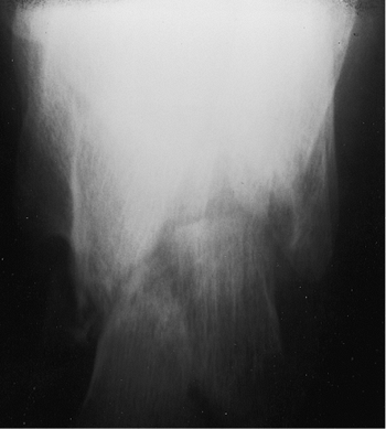
visualized on the foot films. The axial view demonstrates the position
of the tuberosity, the status of the medial wall, and the location of
the fracture(s) through the facet (Fig. 35.2).
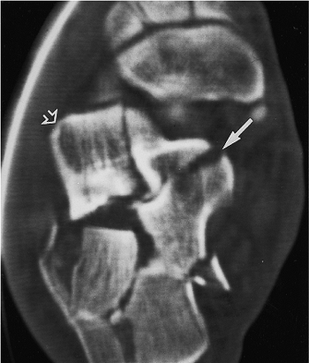
morphology, the surgeon obtains bi-planar computed tomography (CT)
scans with 2- or 3-mm cuts. The scan should include images in the plane
of the foot as well as in a plane perpendicular to the posterior facet
of the talus. The most important of these are the axial images of the
hind foot perpendicular to the posterior facet of the talus. The image
is described in reference to the talus because the posterior facet of
the calcaneus is displaced. This view is obtained with the foot flat on
the table, the knee flexed, and the gantry angled 30 degrees forward.
The axial images are used to classify the fracture and to evaluate the
fracture anatomy. The surgeon should make note of pertinent anatomic
points such as the position and integrity of the tuberosity, the
location and number of fractures in the posterior facet, displacement
of the lateral wall, the location of medial-wall comminution or
fracture lines, the size of the sustentacular fragment, fractures in
the anterior calcaneus, the presence or absence of an anterolateral
fragment, and the position of the peroneal tendons (dislocated or not) (Figs. 35.3 and 35.4).
 |
|
Figure 35.1.
The lateral view of the calcaneus demonstrates a joint-depression fracture with a portion of the posterior facet impacted into the cancellous bone of the tuberosity. The sagittal plane rotation of the displaced posterior facet is best seen on this view. |
 |
|
Figure 35.2.
The axial (Harris) view demonstrates the primary fracture line, medial comminution, the fractures into the facet, and the varus angulation of the tuberosity. |
evaluate the anterior calcaneus and sustentaculum tali. Fractures of
the sustentacular fragment in the coronal plane may decrease the bone
available for fixation of the facet. These fractures may not be seen in
the other radiographs or axial CT scans but are visible on the CT
images of the plane of the foot (Fig. 35.5).
 |
|
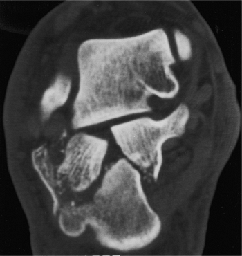
Figure 35.3.
The 30-degree semicoronal CT image demonstrates the comminution and degree of depression of the posterior facet. The separation and step-off are easily seen, but the sagittal plane rotation of the fragments is not well visualized. The wedging effect of the tuberosity fragment separating the facet fragments and the lateral wall blowout is well visualized. |
 |
|
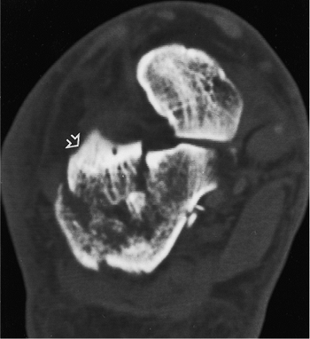
Figure 35.4. A CT image farther anterior demonstrates a separate anterolateral fragment (open arrow).
|
By initially classifying the injury into either a joint depression or
tongue-type fracture, the surgeon can better plan the reduction tactic.
The Sanders classification was devised based on the ease of reduction
and fixation via the lateral approach and has been predictive of
outcome (2,5). The
greater the number of fractures in the facet and the more medial their
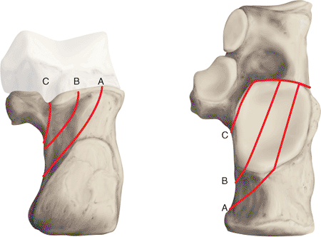
location, the harder will be the reduction. In the Sanders
classification, the fracture lines are designated A through C by their
location from lateral to medial, respectively. In a type 2C fracture,
the entire facet is displaced from the intact medial calcaneus.
understand the anatomy of the fracture, not only as it relates to
displacement but also as it relates to the tactic for surgical
reduction. Two steps are critical in planning the reduction and
fixation of a calcaneal fracture. First are references for reduction,
which include the anteroinferior margin of the facet (the angle of
Gissane), the posterior facet of the
talus,
the intact posterior facet of the calcaneus, the calcaneocuboid joint,
the tuberosity, and the lateral wall. Second are the standard fixation
points used, which include the sustentaculum tali, medial wall,
tuberosity, and anterior calcaneus.
 |
|
Figure 35.5.
The CT scan in the plane of the foot is the best view to evaluate the sustentaculum region. On this CT image, a vertical fracture through the sustentaculum, which is not seen on any other projection, is visible (solid arrow). The displaced lateral portion of the posterior facet is seen to be impacted into the tuberosity adjacent to the sustentacular region. The separate anterolateral fragment is seen on this view as well (open arrow). |
 |
|
Figure 35.6.
The CT classification of Sanders. The fracture is described by the number and location of fracture lines in the posterior facet. Each fracture is given a number and a letter corresponding to the number of fragments of the posterior facet and their location. For example, a 2B fracture has one fracture line in the B location (see Fig. 35.3), and a 3BC has two fracture lines, one in the B position and one in the C position. |
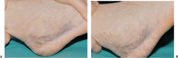 |
|
Figure 35.7. The wrinkle test is done by bringing the foot from the plantarflexed position (A) into dorsiflexion and observing the wrinkles (B) that form on the lateral side of the ankle and foot.
|
the initial postinjury swelling must be resolved. This commonly takes
10 to 21 days to occur but dramatically improves the condition of the
soft tissues. The lateral bulge caused by lateral wall displacement can
be confused with swelling, so the pliability of the skin is a better
characteristic than swelling to test the status of the soft tissues.
blood filled, then they should be allowed to resolve without
intervention. Clear blisters are aspirated and then unroofed several
days later. In either case, blisters are treated as burns once they are
open. Sterile dressings with silver sulfadiazine (Silvadene) cream are
used until epithelialization occurs.
predictor of whether the soft tissue will tolerate surgery. It is
performed by bringing the ankle from a plantar-flexed position to
neutral. If the skin wrinkles, then it is ready for surgery (Fig. 35.7).
Ecchymosis is common and is often distributed along the peroneal
tendons. As long as blisters are absent, this is not a contraindication
to surgery. The foot is kept in a bulky dressing of soft roll and
elevated until the soft tissues will tolerate the surgery. The patient
may be discharged home and the foot examined every 5 days until the
swelling resolves.
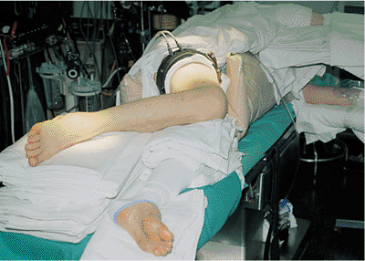
must be obtained prior to surgery. Once soft-tissue swelling has
decreased and skin wrinkling is seen, surgery can be performed. The
patient is placed on the operating room table in the lateral decubitus
position, and a beanbag or some other device is used to maintain torso
stability. The legs are placed apart, in a scissor-like configuration
such that the contralateral down limb is straight, and the operative
limb is bent at the knee. The operative heel should lie at the corner
of the table so that the surgeon can easily access the limb and the
fracture. In addition, this positioning will allow the surgeon to use
the c-arm without superimposition of the opposite leg. The nonoperative
leg
should
have padding placed to protect the peroneal nerve as well as any bony
prominences, and a pillow is placed between the legs (Fig. 35.11).
 |
|
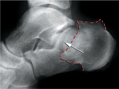
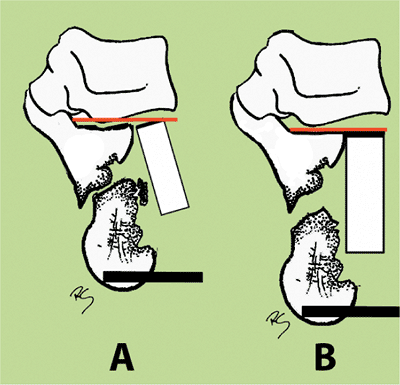
Figure 35.8. Plain radiographs of a joint depression fracture. The depressed joint fragment (white arrow)
is impacted below the stable medial fragment. This creates a double density. The impaction of the posterior tuberosity is noted by the dotted red line. |
 |
|
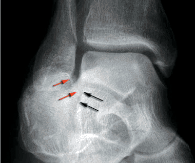
Figure 35.9. Broden’s view of intra-articular fracture. This is a perfect mortise view of the ankle. Primary fracture line is shown by black arrows, and the shifted superolateral fragment is indicated by red arrows.
|
 |
|
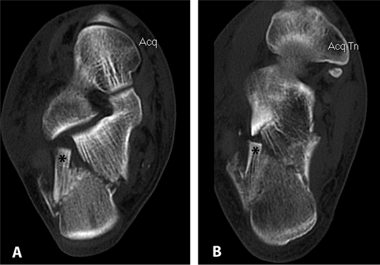
Figure 35.10. CT scan of fracture. The superolateral fragment (*) is seen on both the semicoronal (A) and transverse (B) projections.
|
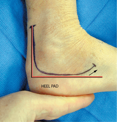
A drawn line is initiated from 2 cm proximal to the tip of the lateral
malleolus, at the lateral edge of the Achilles tendon, and is continued
down toward the plantar surface of the heel. As the surgeon’s pen
approaches the heel pad, the line is curved to parallel the superior
edge of the pad. The marking then follows the pad toward the insertion
of the peroneus brevis tendon, but it should be angled up so that the
surgeon can access the calcaneocuboid joint if needed.
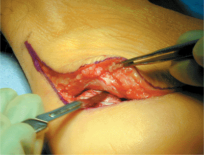
skin incision is made at the proximal part of the vertical limb and
extended plantarly. The incision should become full thickness when the
calcaneal tuberosity is reached, and the surgeon should avoid beveling
the skin when turning the corner with the knife. As the knife parallels
the plantar surface of the foot, pressure is again relaxed and a
layered incision is developed distally.
Earlier use of retractors will tear the skin away from the periosteum,
which could potentially cause late necrosis of the skin.
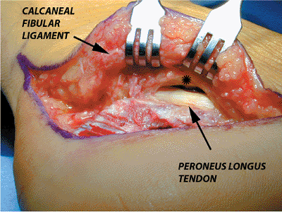
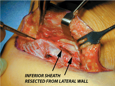
is encountered and resected from the calcaneus; this will expose the
peroneal tendons and their inferior sheath at the level of the peroneal
tubercle. The peroneal tendons must be carefully identified and
retracted, or one or both tendons will be lacerated during the
dissection (Figs. 35.15 to 35.17).
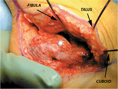
tendons are slightly subluxed anteriorly, and a 1.6-mm Kirschner (K)
wire is then inserted into the fibula to retract the peroneal tendons.
A second K wire is placed in the talar neck to retract the midportion
of the peroneal tendons and the skin flap, and a third K wire is placed
in the cuboid, thereby retracting the distal aspect of the peroneal
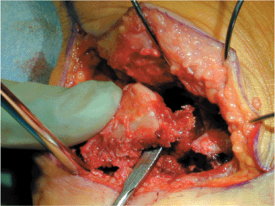
tendons and the full-thickness skin flap. The exposure of the entire
lateral wall can be completed by placing a small retractor into the
sinus tarsi over the anterolateral corner of the calcaneus (Fig. 35.18).
 |
|
Figure 35.11. Positioning of the patient.
|
 |
|
Figure 35.12. Lateral extensile incision (red line, landmarks), (black arrow,
direction of distal end of incision used to access calcaneocuboid joint). Also, the skin has ample wrinkles, indicating that edema is no longer in the skin flap. |
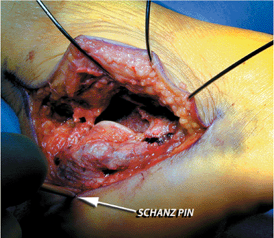
predrilled and a short Schantz pin is screwed into place. Using the
pin, the heel is manipulated and distracted into varus, which
disimpacts the fracture and makes the edge of the fragment more visible
(Fig. 35.19).
 |
|
Figure 35.13. Subperiosteal development of lateral flap.
|
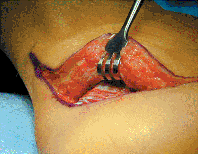 |
|
Figure 35.14. Retractor placed after full thickness flap is developed.
|
 |
|
Figure 35.15. Exposure of peroneal tendons (*, peroneal brevis tendon).
|
 |
|
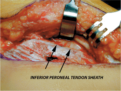
Figure 35.16. Exposure of inferior peroneal-tendon sheath.
|
 |
|
Figure 35.17. Resection of inferior peroneal-tendon sheath from lateral wall, which protects tendons and permits retraction.
|
 |
|
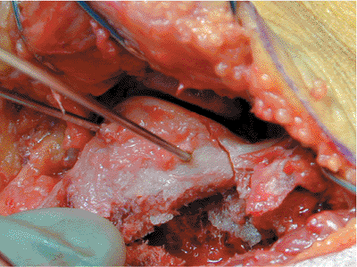
Figure 35.18.
No touch technique in which three 1.6-mm K wires are used for retraction. The lateral wall is fully exposed, and the depressed lateral-joint fragment is visualized (*). |
 |
|
Figure 35.19.
Schantz pin disimpaction of joint. The superolateral fragment is shifted farther away from the medial joint surface than it is in Figure 35.18, which indicates that it is loose. |
 |
|
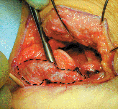
Figure 35.20. Separation of lateral wall (dotted line) from superolateral fragment.
|
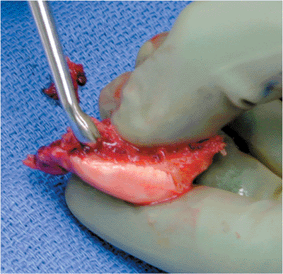
The farthest anterior plantar edge of the depressed superolateral
fragment is located and a small periosteal elevator is placed
underneath it. Disimpaction of the fragment is performed gradually
because sudden strong pressure may result in the fragment falling on
the operating room floor (Fig. 35.21). Once lifted, it should be removed, cleaned of clot, and placed in the same container as the lateral wall.
 |
|
Figure 35.21.
Disimpaction of superolateral fragment. The surgeon’s thumb is holding the fragment laterally to maintain control during manipulation. |
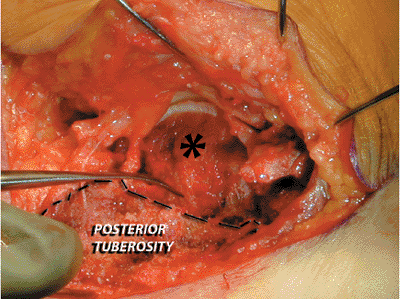
attention is turned to the medial sustentacular component, the
posterior tuberosity, and the primary medial-fracture line (Fig. 35.22).
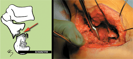
A periosteal elevator is placed into the medial fracture line from the
lateral wound, and the posterior tuberosity is disimpacted from the
sustentaculum (Fig. 35.23).
 |
|
Figure 35.22.
With the superolateral fragment removed, the medial sustentacular (constant) fragment (*) and the posterior tuberosity are easily seen. The primary fracture line, through the medial wall of the calcaneus (elevator), is identified. |
The articular fragment should be repositioned such that height,
rotation, and varus-valgus alignment are correct. This will not be
possible if the fragment hits the edge of the posterior tuberosity;
therefore, the posterior-inferior path for the fragment must be free of
bone. This may require the surgeon to curette excess bone from the
tuberosity, disimpact the tuberosity with excess varus force, or with a
rongeur remove a small amount of bone that is blocking the reduction (Fig. 35.25).
articular fragment is placed. The anterior process may be in as many as
three pieces with the middle fragment pulled proximally by the
interosseous ligament. A laminar spreader placed in the sinus tarsi is
used to stretch the ligament thereby allowing the central piece to be
more easily reduced. The surgeon should avoid ligament resection
because it will destabilize the joint. In addition, a transverse
fracture line may be present at the angle of Gissane. This will rotate
the medial articular fragment beneath the medial-anterior tuberosity
fragment. Before reduction
of
the lateral articular fragment, the medial articular fragment must be
repositioned, or the superolateral fragment will be reduced to a
fragment that itself is not reduced.
 |
|
Figure 35.23. Schematic and clinical view of posterior tuberosity disimpaction (red arrow, direction of insertion of periosteal elevator).
|
 |
|
Figure 35.24. The superolateral fragment is cleaned of clot to assure perfect interposition during reduction.
|
 |
|
Figure 35.25. Schematic showing reduction maneuvers. A.
While articular fragment is repositioned in height, it is still in valgus because the posterior tuberosity is blocking reduction. B. After the tuberosity is pulled out of the way and excess bone is rongeured off, the superolateral fragment now fits in both height and alignment (not shown is the third component of reduction, which shows rotation). |
 |
|
Figure 35.26.
Provisional reduction of the superolateral fragment through use of two K wires to prevent rotation. The fragment is anatomically aligned at the angle of Gissane. |
At this point, the anterior lateral “corner” of the articular fragment
should align with the anterolateral “corner” of the medial
sustentacular fragment. The anterolateral fragment should either fall
in place or be manipulated back into position and held with K wires.
When this reduction is anatomic, the angle of Gissane will be restored.
At this point, verifying that the lateral column is anatomically
reduced, the surgeon places the lateral wall back.
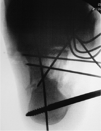
obtain intraoperative lateral, Broden’s, and axial fluoroscopic views.
The lateral should show a true lateral of the talus, thereby
guaranteeing an accurate view of the calcaneus (Fig. 35.27).
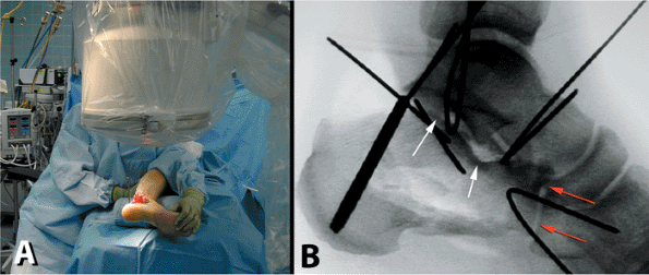
Next, with the fluoroscope in the same position, the leg is externally
rotated 45 degrees and the foot is dorsiflexed. A mortise view of the
ankle is then obtained; it shows the posterior facet in a Broden’s view
(Fig. 35.28). Finally, the leg is externally
rotated 90 degrees, and the foot is maximally dorsiflexed. The
fluoroscope is then angled such that the head is on the plantar aspect
of the mid foot and a clear axial view of the calcaneus is obtained (Fig. 35.29).
 |
|
Figure 35.27. Lateral x-ray. A. Position with C-arm. B. Lateral fluoroscopic view. Anatomic reduction of calcaneal cuboid joint (red arrows), restoration of the angle of Gissane (lower white arrow), and restoration of Bohler’s angle (higher white arrow).
|
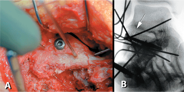
anatomic reduction of the joint is accomplished. Fixation is then
obtained using a 3.5-mm cortical screw placed in a lag mode. The screw
should be directed from the lateral cortex and aimed slightly plantar
to avoid violation of the intra-articular surface; it should extend
distally toward the sustentaculum (Fig. 35.30). Once the screw is placed, the joint should be reassessed both visually and fluoroscopically.
 |
|
Figure 35.28. Broden’s view. A. Positioning with the limb externally rotated 45 degrees and dorsiflexed. B. Mortise view of the ankle will provide best view, but the joint is still gapped and not anatomically reduced (white arrow).
|
 |
|
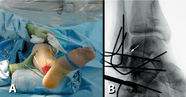
Figure 35.29.
Axial view showing repositioning of posterior tuberosity through use of axial K wire to maintain position. The tuberosity is not yet completely reduced out of varus. |
anterolateral fragment and the posterior tuberosity are realigned to
insure that the body is anatomically reduced. The small lateral-wall
fragment is elevated so the surgeon can evaluate the cancellous defect
below the joint. If a large cavity is present, the surgeon may elect to
fill the void with either bone graft or a graft substitute. The lateral
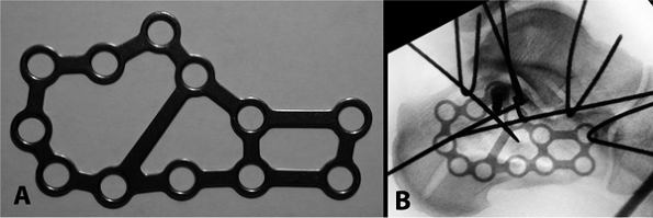
wall remnant is then repositioned, and a low-profile, lateral,
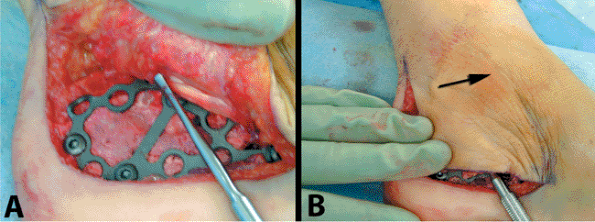
neutralization plate is selected. One of the authors (RS) has developed
a specific plate for this and uses it exclusively (Fig. 35.31). Bending of the plate is not recommended because this will throw the calcaneal tuberosity into varus.
 |
|
Figure 35.30. Definitive fixation of articular surface. A. Lag screw (3.5 mm) is placed with antirotation K wires in place. B. X-ray verifies anatomic joint reduction. Gap is closed and the articular surface is aligned perfectly (white arrow).
|
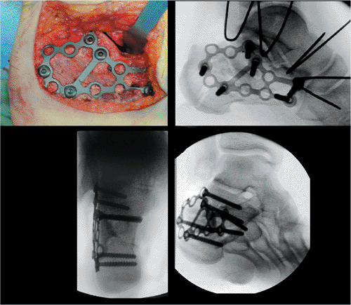
lateral fluoroscopic view, cancellous fully threaded 4.0-mm screws are
used to secure the three main components of the calcaneus: the anterior
process, the posterior tuberosity, and the joint. The final reduction
is verified fluoroscopically, and all K wires are removed (Fig. 35.32).
 |
|
Figure 35.31. A. Low-profile, calcaneal, perimeter plate (ACE-DePuy, Warsaw, IN). B.
Positioning of plate on lateral calcaneus and verification of size through use of fluoroscopy. In this case, a larger plate should be selected. |
evaluated to make sure they were not dislocated from the injury. A
Freer elevator is placed into the peroneal tendon sheath at the distal
inferior portion of the wound. It should advance within the sheath
easily. While watching the skin, the surgeon pushes the elevator
forward in an attempt to slip it over the malleolar tip. If he/she is
successful, the sheath has been torn off the fibula (Fig. 35.33),
and a repair must be performed. To expose the tendon sheath, a small
incision (< 3 cm) is made in the skin over the posterior edge of the
distal tip of the fibula. Using one or two suture anchors, the sheath
is secured to the bone and the repair is tested. Once completed, the
tendons will no longer dislocate over the edge of the fibula.
 |
|
Figure 35.32. Plate in position with final x-rays showing anatomic reduction of the fracture.
|
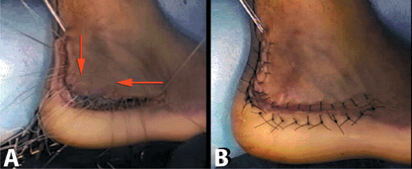
the vertical limb of the incision, and the wound is closed in a layered
fashion. Deep figure-of-eight, individual, no. 0, absorbable sutures
are placed in the corner of the wound. The surgeon works out to the end
of each limb of the incision. The sutures are not tied but rather
clamped until all deep sutures have been placed. Then, starting at the
proximal and distal ends and working toward the corner of the incision,
the surgeon hand ties the sutures sequentially; this technique will
pull the flap and thus take tension off the corner of the wound, which
is the most susceptible to wound necrosis. The skin is closed with no.
3 nylon suture using the modified Allgöwer-Donati technique: The
surgeon starts again at the ends and progresses toward the apex (Fig. 35.34). Sterile dressings are applied and the tourniquet is deflated. A bulky cotton dressing and Weber splint are then placed.
are obtained the next day, and the drain is removed. The patient is
then placed in a short-leg nonweight-bearing cast and discharged home.
The patient is seen in the office for wound checks and cast exchanges.
The sutures are removed only if the incision is fully sealed, usually
between 4 and 6 weeks.
 |
|
Figure 35.33. Evaluation of the peroneal tendon sheath. A. The insertion of an elevator into the sheath. B. An attempt is made to sweep the elevator over the fibula (arrow). This was not possible in this case.
|
stocking and fracture boot that is locked in neutral flexion. Early
subtalar joint range-of-motion exercises out of the boot are initiated
at this time; however, weight bearing is not permitted until 12
postoperative weeks have passed. If ceramic cement had been used to
fill the void, weight bearing may be initiated earlier, typically at 6
weeks, but only if the wound has completely healed. In addition, we
prefer that the patient sleep in the boot until weight bearing is
initiated so that an equinus contracture is prevented. Once weight
bearing is initiated, the patient is gradually transitioned into
regular shoes as tolerated. Physical therapy, specifically for gait
training and achieving balance, is also begun at this point. The
patient is able to return to normal activity at 6 postoperative months.
 |
|
Figure 35.34. Wound closure. A. Figure-of-eight, interrupted, no. 0 Vicryl (Ethicon, Rutherford, NJ) are placed and tied from edges to corner (red arrows). B. Wound closure via an Allgöwer-Denoti stitch with no. 3 nylon. The knots are placed on the outside.
|
 |
|
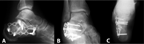
Figure 35.35. Final x-rays. A. Lateral view. B. Broden’s view. C. Axial view.
|
 |
|
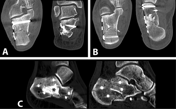
Figure 35.36. Postoperative CT scans. A. Coronal cuts. B. Transverse cuts. C. Sagittal reconstructions showing body reposition. Calcium phosphate cement was used as void filler (*).
|
RE, Meek RN. Comparison of open versus closed reduction of
intraarticular calcaneal fractures: a matched cohort in workmen. J Orthop Trauma 1992;6(1):216.
R, Fortin P, DiPasquale T, et al. Operative treatment in 120 displaced
intraarticular calcaneal fractures: results using a prognostic computed
tomography scan classification. Clin Orthop 1993;290:87.